Polishing device for wooden spoon production
A technology of a wooden spoon and a grinding mechanism, which is applied to grinding drive devices, grinding/polishing safety devices, grinding machines, etc., can solve the problems of cumbersome operation process, labor-intensive, low work efficiency, etc., and achieve simple operation and improve work efficiency. , the effect of saving manpower
- Summary
- Abstract
- Description
- Claims
- Application Information
AI Technical Summary
Problems solved by technology
Method used
Image

Examples
Embodiment 1
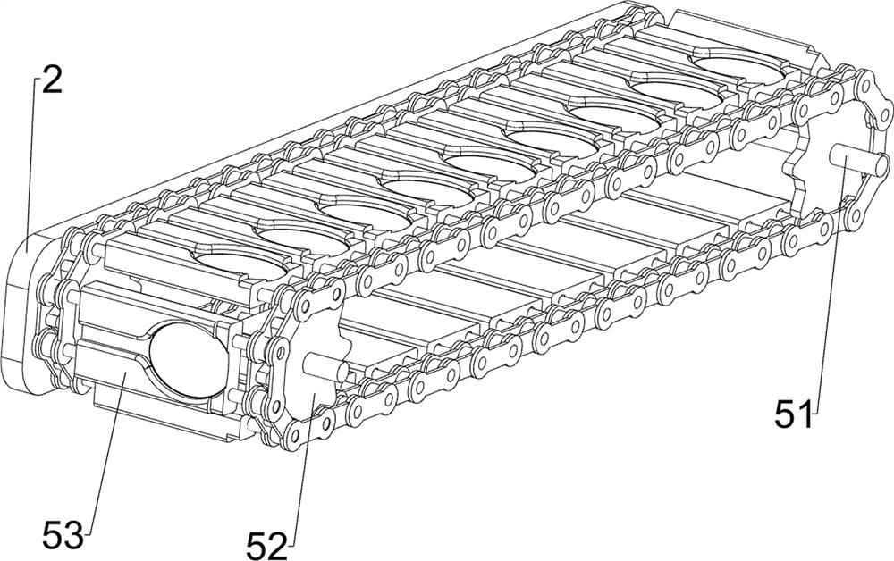
[0028] A grinding device for wooden spoon production, such as Figure 1 to Figure 4 As shown, it includes a support leg 1, a guard plate 2, a storage plate 3 and a support frame 4, and a guard plate 2 is connected between the tops of the two legs 1 on both sides. The front side of the protective plate 2 is connected with a storage plate 3, and the top of the storage plate 3 is connected with a support frame 4, and also includes a feeding mechanism 5, a transmission mechanism 6, a grinding mechanism 7 and a dust collection mechanism 8, and the protective plate 2 is provided with a feeding mechanism 5. A transmission mechanism 6 is provided between the storage plate 3 and the support frame 4 , a grinding mechanism 7 is provided between the transmission mechanism 6 and the support frame 4 , and a dust suction mechanism 8 is provided on the storage board 3 .
[0029] The feeding mechanism 5 includes a first rotating shaft 51, a conveyor belt 52 and a discharge plate 53, and the fi...
Embodiment 2
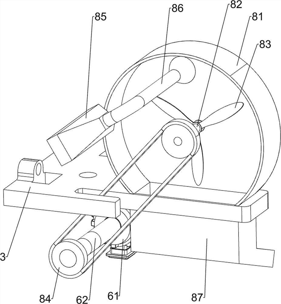
[0036] On the basis of Example 1, such as image 3 As shown, the transmission mechanism 9 is also included, and the transmission mechanism 9 includes the second belt transmission group 91, the sixth rotating shaft 92, the third bevel gear 93, the seventh rotating shaft 94, the sector gear 95 and the full-toothed gear 96, and the storage plate 3 The top is rotatably connected with a sixth rotating shaft 92, and a second belt transmission group 91 is wound between the sixth rotating shaft 92 and the third rotating shaft 67. The front side of the front side guard plate 2 is rotatably connected with a seventh rotating shaft 94, and the seventh rotating shaft 94 and the sixth rotating shaft 92 are connected with a third bevel gear 93, the two third bevel gears 93 mesh with each other, the seventh rotating shaft 94 is connected with a sector gear 95, and the first rotating shaft 51 on the right is connected with a full tooth gear 96, sector gear 95 can mesh with full tooth gear 96. ...
Embodiment 3
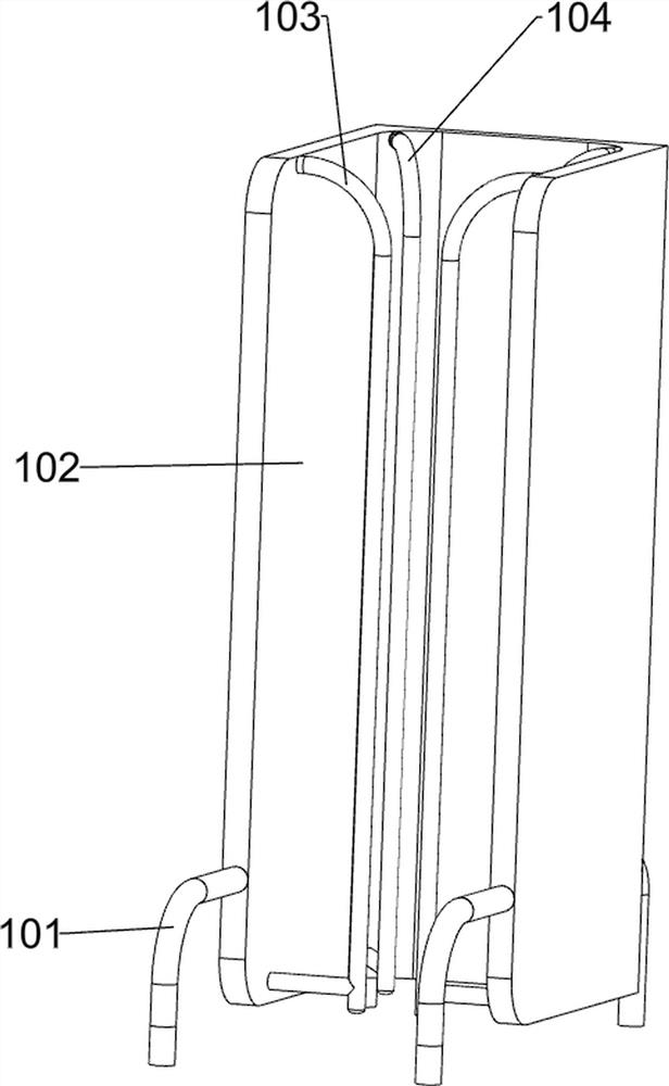
[0039] On the basis of Example 2, such as Figure 5 As shown, it also includes a discharge mechanism 10, the discharge mechanism 10 includes a fixed rod 101, a discharge frame 102, a first positioning rod 103 and a second positioning rod 104, and the left side of the top of the two side guard plates 2 is connected with two There are four fixed rods 101, and a discharge frame 102 is connected between the four fixed rods 101, and a first positioning rod 103 and a second positioning rod 104 are connected to both side walls of the discharge frame 102.
[0040] When placing wooden spoons, the wooden spoons can be stacked and placed in the discharge frame 102, and positioned by the first positioning rod 103 and the second positioning rod 104, when the discharge plate 53 rotates to the bottom of the discharge frame 102, the discharge The lowermost wooden spoon in the frame 102 will fall on the discharging frame 102, so that manual work is not required to frequently place the wooden s...
PUM
 Abstract
Description
Claims
Application Information
 - R&D
- Intellectual Property
- Life Sciences
- Materials
- Tech Scout
- Unparalleled Data Quality
- Higher Quality Content
- 60% Fewer Hallucinations
Browse by: Latest US Patents, China's latest patents, Technical Efficacy Thesaurus, Application Domain, Technology Topic, Popular Technical Reports.
© 2025 PatSnap. All rights reserved.Legal|Privacy policy|Modern Slavery Act Transparency Statement|Sitemap|About US| Contact US: help@patsnap.com