Automobile clutch assembling tool

A technology for assembling tooling and clutches, which is applied to manufacturing tools, workpiece clamping devices, hand-held tools, etc., can solve problems such as troublesome adjustment methods and unfavorable use by operators, and achieve the effect of improving assembly quality and expanding the scope of use.

Inactive Publication Date: 2021-03-19
WUHU DAJIE CLUTCH
View PDF7 Cites 6 Cited by
  • Summary
  • Abstract
  • Description
  • Claims
  • Application Information

AI Technical Summary

Problems solved by technology

[0004] The object of the present invention is the automobile clutch assembly tool, to solve the problem that the existing universal clutch assembly tool proposed in the above-mentioned background technology is in use, because the position of the clamp block is adjusted by using a wrench to rotate the small bevel gear. The method is cumbersome, which causes the problem of not using the operator

Method used


Image

  • Automobile clutch assembling tool
  • Automobile clutch assembling tool
  • Automobile clutch assembling tool

Examples


Embodiment 1

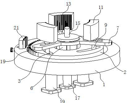
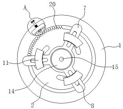
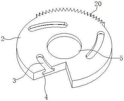
[0029] Such as Figure 1-9 As shown, the present invention provides a technical solution: automobile clutch assembly tooling, including a base 1 and a turntable 2, the top of the turntable 2 is provided with an arc-shaped chute 3, and both sides of the arc-shaped chute 3 are connected with a limit groove 4, The top of the turntable 2 is provided with a cavity 5, the inside of the base 1 is fixedly installed with a telescopic connecting plate 6, the top of the telescopic connecting plate 6 is fixedly installed with a tray 7, and the inside of the tray 7 is provided with a strip groove 8, the strip groove The inside of 8 is equipped with a push rod 9, the bottom of the push rod 9 is movably installed inside the arc chute 3, the bottom of the push rod 9 is fixedly installed with a limit block 10, and the limit block 10 is movably installed in the position of the limit groove 4. Inside, the top of the push rod 9 is movable with a clamping block 11, the inside of the clamping block...

Embodiment 2

[0032] Such as Figure 1-9 As shown, on the basis of the first embodiment, the present invention provides a technical solution: the number of telescopic connecting plates 6 is not less than two, and the distribution is evenly located inside the cavity 5 .

[0033] In this embodiment, by setting no less than two telescopic connecting plates 6, it is beneficial to stably support the tray 7, so that the tray 7 can stably support the clutch, which is beneficial to the installation of the clutch.

Embodiment 3

[0035] Such as Figure 1-9 As shown, on the basis of Embodiment 1 and Embodiment 2, the present invention provides a technical solution: there are three bar-shaped grooves 8, which are evenly distributed inside the tray 7, and the number of arc-shaped chutes 3 is three. , and evenly distributed on the top of the turntable 2.

[0036] In this embodiment, there are three clamping blocks 11. By using the three clamping blocks 11, the clutch is clamped in three different directions, which is beneficial to the stable fixation of the clutch and avoids the displacement of the clutch during the assembly process. Condition.


PUM


Abstract

The invention discloses an automobile clutch assembling tool which comprises a base and a rotary disc. An arc-shaped sliding groove is formed in the top of the rotary disc, a push rod is movably installed in a strip-shaped groove, a limiting block is fixedly installed at the bottom of the push rod, a clamping block is movably installed at the top of the push rod, and a telescopic rod is fixedly installed at the bottom of a lifting disc; and a first cylinder is fixedly mounted at the bottom of the telescopic rod, a fixed disc sleeves the bottom of the rotary disc in a connected manner, second cylinders are fixedly mounted at the two ends of the bottom of the base, first fixed teeth are fixedly mounted at one side of the rotary disc, and a locking device is fixedly mounted at one end of thetop of the base. A driving disc, an outer tooth friction plate, an inner tooth plate, a clutch spring and a pressing disc are sequentially placed at the top of a tray, a tool capable of abutting against the pressing disc is placed at the top of the pressing disc, a second air cylinder is used for enabling the tray to move upwards, the pressing disc abuts against the bottom of the tool, and therefore compression of the clutch spring is achieved; and the first cylinder jacks a clutch, so that the driven disc is arranged on the clutch in a sleeving manner, and assembly of the clutch is completed.

Description

technical field [0001] The invention belongs to the technical field of clutch assembly, and in particular relates to an automobile clutch assembly tool. Background technique [0002] The clutch is located in the flywheel housing between the engine and the gearbox, and the clutch assembly is fixed on the rear plane of the flywheel with screws, and the output shaft of the clutch is the input shaft of the gearbox. During the driving process of the car, the driver can step on or release the clutch pedal as needed to temporarily separate and gradually engage the engine and the transmission, so as to cut off or transmit the power input from the engine to the transmission. Clutches are common components in mechanical transmissions that can disengage or engage the transmission system at any time. [0003] Most of the existing clutches are installed by hand. When assembling, just put the clutch driven disc and clutch cover assembly on the flywheel, and locate through the positioning...

Claims


Application Information

Patent Timeline
Patent Type & Authority Applications(China)
IPC IPC(8): B25B11/00B25B27/00
CPCB25B11/00B25B27/0064
Inventor 董祥辉何冠侯俞明田瑞毕承琪吴安琦
Owner WUHU DAJIE CLUTCH
Why Eureka
Try Eureka