Office binding machine

A technology of binding machine and machine head, which is applied in binding and other directions, and can solve problems affecting the binding of book pages, different contact areas, and inclination

Inactive Publication Date: 2021-03-19
林伟
View PDF0 Cites 0 Cited by
  • Summary
  • Abstract
  • Description
  • Claims
  • Application Information

AI Technical Summary

Problems solved by technology

[0005] Aiming at the deficiencies in the prior art, the purpose of the present invention is to provide an office binding machine to solve the problem in the prior art that the single-hole binding always drills the corner ends of the page files, and the corner ends will form a bottom-to-bottom The crossing of the groove makes the

Method used


Image

  • Office binding machine
  • Office binding machine
  • Office binding machine

Examples


Embodiment 1

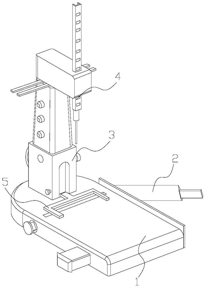
[0028] Example 1: Please refer to Figure 1-Figure 5 , the specific embodiments of the present invention are as follows:

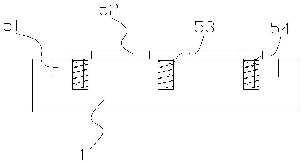
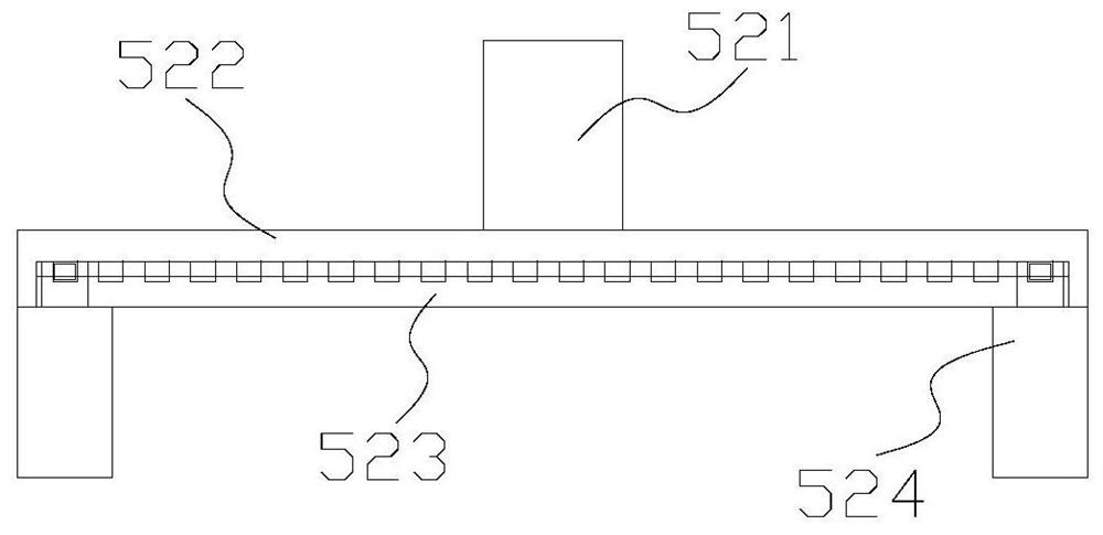
[0029] Its structure includes a workbench 1, a cutter 2, a machine head 3, a punching frame 4, and a limit structure 5. The cutter 2 is installed on the side end of the workbench 1 and connected by a hinge, and the machine head 3 is installed vertically. It is welded to the upper end of the workbench 1, the punching frame 4 is embedded in the inner side of the machine head 3 and is mechanically connected, and the limiting structure 5 is horizontally installed on the upper end of the workbench 1 and below the punching frame 4; The bit structure 5 includes a bottom groove 51, a limiting plate 52, a movable groove 53, and a movable rod 54. The bottom groove 51 is recessed inside the workbench 1 and is an integrated structure. The limiting plate 52 is horizontally arranged above the bottom groove 51 and Arresting against the upper end of the workbench 1, the ...

Embodiment 2

[0035] Example 2: Please refer to Figure 5-Figure 8 , the specific embodiments of the present invention are as follows:

[0036] The pressure plate 24a includes a plate body a1, a guard plate a2, an extension a3, a friction block a4, and an adaptation block a5. The guard plate a2 is vertically installed on the front of the plate body a1 and is fixedly connected, and the extension a3 is arranged on the plate body The side end of a1 is an integrated structure, the friction block a4 is installed on the front of the plate a1 and distributed at intervals, and the adapting block a5 is evenly installed on the front of the plate a1 and spaced from the friction block a4.

[0037] refer to Figure 6 The adaptable block a5 includes an outer edge a51, a movable cover a52, a limit plate a53, and a fitting plate a54. The movable cover a52 is installed on the inner side of the outer edge a51 and is fixedly connected, and the fitting plate a54 is embedded in the movable cover a52 The inner...


PUM


Abstract

The invention discloses an office binding machine which structurally comprises a workbench, a cutter, a machine head, a punching frame and a limiting structure. The cutter is installed at the side endof the workbench, the machine head is vertically installed at the upper end of the workbench, the punching frame is embedded into the inner side of the machine head, the limiting structure is horizontally installed at the upper end of the workbench, and the limiting structure comprises a bottom groove, a limiting plate, a movable groove and a movable rod; and the bottom groove is sunken in the inner side of the workbench, the limiting plate is horizontally arranged above the bottom groove, the movable groove is embedded in the inner side of the workbench, the movable rod is embedded in the inner side of the movable groove, the spring is arranged between the movable rod and the movable groove, and the upper end of the movable rod and the lower end of the limiting plate are fixed. Accordingto the office binding machine, the limiting structure is installed at the upper end of the workbench, so that the limiting structure adapts to page files, and the moving area is reduced, so that drilling is better conducted, and displacement is prevented; and an adaptive block is arranged on the front surface of a plate body, so that the contact area with the page files is increased, the stress during drilling is increased, and the stability during drilling is ensured.

Description

technical field [0001] The invention belongs to the office field, and in particular relates to an office binding machine. Background technique [0002] In order to organize the documents such as book pages, in order to ensure the neat arrangement of these documents and the convenience of reading, these book page documents need to be bound, and there are various methods of binding, including single-hole binding, and then need to use To the office binding machine, these office page files are bound and arranged, but there are following deficiencies in the prior art: [0003] Since the single-hole binding is to drill the corners of the page files, and the corners will form a span to the bottom groove, so that the contact area across the two ends of the bottom groove is different, and then when the pressure is drilled, the Along with the direction of its force, it drives the corners with smaller contact area to move to the bottom groove, resulting in inclined drilling, which aff...

Claims


Application Information

Patent Timeline
IPC IPC(8): B42B5/02
CPCB42B5/02
Inventor 林伟
Owner 林伟
Why Eureka
Try Eureka