Al technical title is built by PatSnap Al team. It summarizes the technical point description of the patent document.
A technology for anti-collision guardrails and highway bridges, which is applied in bridge construction, road safety devices, bridges, etc. Effect
Inactive Publication Date: 2021-03-19
广州佳优华信息科技有限公司
View PDF0 Cites 1 Cited by
Summary
Abstract
Description
Claims
Application Information
AI Technical Summary
This helps you quickly interpret patents by identifying the three key elements:
Problems solved by technology
Method used
Benefits of technology
Problems solved by technology
[0003] Based on the inventor's discovery above, the existing a kind of road bridge safety anti-collision guardrail equipment mainly has the following deficiencies, such as: because most of the guardrails are fixedly connected, when the car loses control and crashes into the guardrail at an angle of inclination, the If the end face of the car is not buffered, the car will rebound through the guardrail, so that the body will continue to drive forward for a certain distance through inertia, causing the car to rear-end the front-end vehicle, thereby increasing the severity of the accident
Method used
Image
Click on the blue label to locate the original text in one second.
Reading with bidirectional positioning of images and text.
Examples
Embodiment 1
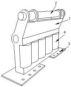
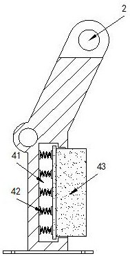
[0026] Example 1: Please refer to Figure 1-Figure 5 , the specific embodiments of the present invention are as follows:
[0027] Its structure includes a main bracket 1, a protective rod 2, a fixed seat 3, and a buffer device 4. A protective rod 2 is installed on the top of the main bracket 1, and two fixed seats 3 are provided, and they are respectively welded to the bottom of the main bracket 1. At both ends of the bottom, the buffer device 4 is provided with five and arranged transversely on the front end of the main bracket 1. The buffer device 4 includes a sliding groove 41, a return spring 42, and a buffer block 43. The sliding groove 41 is arranged on the buffer device 4, five return springs 42 are installed vertically inside the sliding groove 41, and the buffer block 43 is engaged in the sliding groove 41 and is movably matched with the return spring 42.
[0028] The buffer block 43 includes a support body 431, a protective layer 432, and a rubber pad 433. The outer...
Embodiment 2
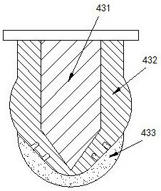
[0032] Example 2: Please refer to Figure 6-Figure 8 , the specific embodiments of the present invention are as follows:
[0033] The rubber pad 433 includes a fixed block b1, an iron sheet b2, an empty groove b3, and a friction groove b4. There are four fixed blocks b1, and the fixed block b1 is engaged with the protective layer 432. The empty groove b3 is provided with There are three, and they are arranged at the inner end of the rubber pad 433. There are six friction grooves b4, and they are arranged around the bottom of the rubber pad 433. out of shape.
[0034] The empty groove b3 includes a groove body b31, a limiting block b32, and a deformation groove b33. Six limiting blocks b32 are arranged at both ends of the groove body b31, and are arranged in groups of three horizontally on both sides of the groove body b31. end, the end faces between the limit blocks b32 are aligned, the deformation groove b33 is provided with four, and are respectively located between two li...
PUM
Abstract
The invention discloses highway bridge safety anti-collision guardrail equipment which structurally comprises a main support, protective rods, fixing seats and five buffer devices, the protective rodsare installed at the top of the main support, the two fixing seats are welded to the two ends of the bottom of the main support respectively, and the five buffer devices are transversely arranged atthe front end of the main support. Each buffer device comprises a sliding groove, a reset spring and a buffer block, each buffer block comprises a supporting body, a protective layer and a rubber pad,each protective layer comprises a protective body, a clamping groove, an installation base, a guide rotating roller and an installation groove, and each guide rotating roller comprises a main rotating roller body, a rubber layer, a protruding block and a rotating shaft. According to the equipment, the five buffer devices are arranged at the end surface of the main support. And a reset spring in the buffer device is movably matched with a buffer block, so that the automobile can be buffered when colliding with the buffer block, the running speed of the automobile is reduced through the multiple buffer devices, and the situation that the automobile collides with the guardrail and is out of control, and rear-end collision is caused to the front-end automobile is avoided.
Description
technical field [0001] The invention relates to the field of bridges, in particular to a safety anti-collision guardrail device for highway bridges. Background technique [0002] As the number of cars continues to increase, the number of car accidents also continues to increase. Car accidents on bridges tend to fall off the bridge. Therefore, guardrails should be installed at both ends of the bridge to block cars and reduce the severity of accidents. The end faces of the guardrails are generally equipped with reflective sheets to warn the vehicles. [0003] Based on the inventor's discovery above, the existing a kind of road bridge safety anti-collision guardrail equipment mainly has the following deficiencies, such as: because most of the guardrails are fixedly connected, when the car loses control and crashes into the guardrail at an inclined angle, the If the end face of the car is not buffered, the car will rebound through the guardrail, so that the body will continue t...
Claims
Application Information
Patent Timeline
Application Date:The date an application was filed.
Publication Date:The date a patent or application was officially published.
First Publication Date:The earliest publication date of a patent with the same application number.
Issue Date:Publication date of the patent grant document.
PCT Entry Date:The Entry date of PCT National Phase.
Estimated Expiry Date:The statutory expiry date of a patent right according to the Patent Law, and it is the longest term of protection that the patent right can achieve without the termination of the patent right due to other reasons(Term extension factor has been taken into account ).
Invalid Date:Actual expiry date is based on effective date or publication date of legal transaction data of invalid patent.