Supercharge Your Innovation With Domain-Expert AI Agents!

Hydraulic crimping pliers

A crimping pliers, hydraulic technology, applied in the direction of connecting/terminating cable equipment, etc., can solve the problems of reducing implementation efficiency, increasing on-site construction risks, and unable to meet the requirements of crimping of various wire diameters.

Active Publication Date: 2021-03-19
JIANGMEN POWER SUPPLY BUREAU OF GUANGDONG POWER GRID
View PDF7 Cites 0 Cited by
  • Summary
  • Abstract
  • Description
  • Claims
  • Application Information

AI Technical Summary

Problems solved by technology

[0002] In the operation and maintenance of power facilities and daily operations, cable crimping pliers are often used for cable crimping. The existing crimping pliers need to be operated with different crimping dies according to the diameter of the crimping cable during use. For the complex and changeable field environment, changing the crimping mold greatly increases the risk of on-site construction and reduces the implementation efficiency. It cannot meet the requirements of conventional crimping of various wire diameters with one pliers on site. Therefore, it is necessary to design a crimping pliers to meet the requirements. On-site construction needs
[0003] Chinese patent CN201920985607.8 discloses a cable crimping pliers for power engineering, including: a cable crimping pliers body, a circular sleeve and a fixed pliers body, the front end of the cable crimping pliers body is provided with a U-shaped opening, And the inner side of the U-shaped opening is slidably connected with a movable pliers body, the tail end of the cable crimping pliers body is embedded with a fixed sleeve, and the circular sleeve is embedded and connected to the fixed sleeve, and the circular sleeve A hydraulic telescopic rod is installed on the inner side. In this solution, the crimping pliers can only meet the crimping requirements of a limited number of wire diameters.

Method used


Image

  • Hydraulic crimping pliers
  • Hydraulic crimping pliers
  • Hydraulic crimping pliers

Examples


Embodiment Construction

[0024] The present invention will be further described below in combination with specific embodiments. Wherein, the accompanying drawings are for illustrative purposes only, and represent only schematic diagrams, rather than physical drawings, and should not be construed as limitations on this patent; in order to better illustrate the embodiments of the present invention, some parts of the accompanying drawings may be omitted, Enlargement or reduction does not represent the size of the actual product; for those skilled in the art, it is understandable that some well-known structures and their descriptions may be omitted in the drawings.

[0025] In the drawings of the embodiments of the present invention, the same or similar symbols correspond to the same or similar components; The orientation or positional relationship indicated by etc. is based on the orientation or positional relationship shown in the drawings, and is only for the convenience of describing the present inven...


PUM


Abstract

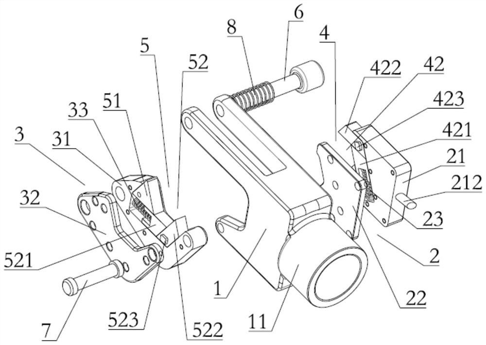
The invention relates to the technical field of cable crimping pliers, in particular to hydraulic crimping pliers. The pilers comprise a body, an opening is formed in the front end of the body, a second plier body is arranged at the opening, a first plier body is arranged in the body, a hydraulic telescopic rod is connected to one side of the first plier body, the pilers also comprise a first guide box arranged in the body and a second guide box arranged at the opening, one end of the first plier body is fixed to the first guide box, the other end of the first plier body is connected to the first guide box in a sliding mode, one end of the second plier body is fixed to the second guide box, the other end of the second plier body is connected to the second guide box in a sliding mode, one end of the first plier body extrudes the other end of the second clamp body, and one end of the second plier body extrudes the other end of the first plier body. The hydraulic crimping pliers can change crimping calibers in a stepless mode according to crimping cable diameters, and can meet crimping requirements of various cable diameters without replacing dies.

Description

technical field [0001] The invention relates to the technical field of cable crimping pliers, in particular to a hydraulic crimping pliers. Background technique [0002] In the operation and maintenance of power facilities and daily operations, cable crimping pliers are often used for cable crimping. The existing crimping pliers need to be operated with different crimping dies according to the diameter of the crimping cable during use. For the complex and changeable field environment, changing the crimping mold greatly increases the risk of on-site construction and reduces the implementation efficiency. It cannot meet the requirements of conventional crimping of various wire diameters with one pliers on site. Therefore, it is necessary to design a crimping pliers to meet the requirements. On-site construction needs. [0003] Chinese patent CN201920985607.8 discloses a cable crimping pliers for power engineering, including: a cable crimping pliers body, a circular sleeve and...

Claims


Application Information

Patent Timeline
IPC IPC(8): H02G1/14
CPCH02G1/14
Inventor 谭健强方振曾宪锋许炳焕谭永康郑铭浩郑飘吴俊杰陈军球黄兢诗甄威扬梁永芳余富贤梁风华
Owner JIANGMEN POWER SUPPLY BUREAU OF GUANGDONG POWER GRID
Features
  • R&D
  • Intellectual Property
  • Life Sciences
  • Materials
  • Tech Scout
  • Unparalleled Data Quality
  • Higher Quality Content
  • 60% Fewer Hallucinations
Learn More