A kind of grouting device and using method for tunnel bridge construction
A bridge construction and tunnel technology, applied in clay preparation devices, cement mixing devices, chemical instruments and methods, etc., can solve problems such as lack of mixing measures in grouting devices, and achieve the effect of full grouting
- Summary
- Abstract
- Description
- Claims
- Application Information
AI Technical Summary
Problems solved by technology
Method used
Image
Examples
specific Embodiment approach 1
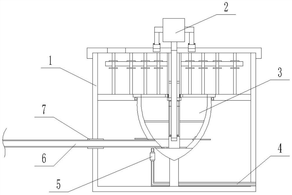
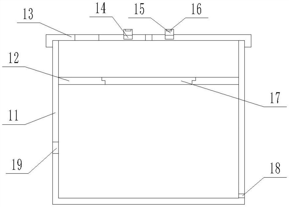
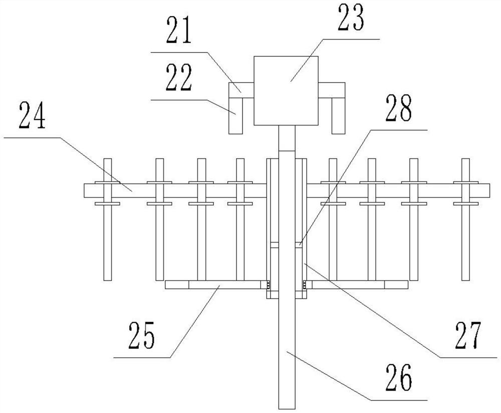
[0029] Specific implementation mode one: as Figure 1-Figure 12 As shown, this embodiment describes a grouting device for tunnel and bridge construction, including a casing 1, a rotating device 2, a discharge device 3, a cleaning water pipe 4, a water pump 5, a discharge pipe 6 and a connecting pipe 7; 1 includes a storage barrel 11, a partition plate 12, a cover 13, and a screw rod 15; the inner middle position of the storage barrel 11 is fixedly connected with a partition plate 12; the center of the partition plate 12 is provided with a circular platform groove 17; The lower end of the right side of the storage barrel 11 is provided with a through hole I18, and the left side of the storage barrel 11 is provided with a through hole II19; the center of the cover 13 is provided with a shaft hole, and the cover 13 is provided with two mutually symmetrical threaded holes 14 , the cover 13 is also provided with a feeding port; the screw 15 is threadedly connected in the threaded h...
specific Embodiment approach 2
[0033] Specific implementation mode two: as Figure 4As shown, this embodiment is a further description of Embodiment 1. The stirring device 24 includes a connecting rod 241, a stirring rod 242, two baffles 243, and a sliding rod 244; one end of the connecting rod 241 is fixedly connected to On the outer circular surface of the sleeve 27, and the connecting rod 241 is vertically provided with a plurality of slideways; the upper and lower ends of the slide rod 244 are fixedly connected with a baffle plate 243, and the slide rod 244 slides with the slideway Matching; the other end of the baffle plate 243 is fixedly connected with the stirring rod 242 . When the sleeve 27 moves downward, the connecting rod 241 slides on the slide bar 244 to avoid affecting the downward movement of the sleeve 27 and further affecting the connection between the sleeve 27 and the discharge device 3 .
specific Embodiment approach 3
[0034] Specific implementation mode three: as Figure 5 , 6 As shown, this embodiment is a further description of specific embodiment 1. The shielding device 25 includes an outer ring 251, an inner ring 252, an elastic circular plate 253, a connecting block I 254, and a connecting block II 255; The two ends of the plate 253 are ring-shaped after being in contact with each other; the connecting block I254 is fixedly connected to the inner circular surface of one end of the elastic circular plate 253, and the connecting block I254 is fixedly connected to the outer circular surface of the inner ring 252; The connecting block II 255 is fixedly connected to the outer circular surface of the other end of the elastic circular plate 253, and the connecting block II 255 is fixedly connected to the inner circular surface of the outer ring 251; the outer ring 251 is fixedly connected to the inner upper end of the circular platform groove 17; The inner ring 252 is connected to the outer ...
PUM
 Abstract
Description
Claims
Application Information
 - R&D
- Intellectual Property
- Life Sciences
- Materials
- Tech Scout
- Unparalleled Data Quality
- Higher Quality Content
- 60% Fewer Hallucinations
Browse by: Latest US Patents, China's latest patents, Technical Efficacy Thesaurus, Application Domain, Technology Topic, Popular Technical Reports.
© 2025 PatSnap. All rights reserved.Legal|Privacy policy|Modern Slavery Act Transparency Statement|Sitemap|About US| Contact US: help@patsnap.com


