Electronic equipment

A technology of electronic equipment and wear-resistant blocks, which is applied in branch office equipment, telephone communications, electrical components, etc., can solve the problems of large space occupation of the lifting mechanism, affect the shooting effect, and occupy a large space, so as to improve the appearance expressiveness and stack design Flexible, reduced interior space effect

Pending Publication Date: 2021-03-23
OPPO CHONGQING INTELLIGENT TECH CO LTD
View PDF0 Cites 0 Cited by
  • Summary
  • Abstract
  • Description
  • Claims
  • Application Information

AI Technical Summary

Problems solved by technology

[0002] In related technologies, there are mainly two ways to combine the anti-wear point on the back of the casing of mobile phones and other terminal devices and the flashlight: one is that the flashlight is hidden inside the device through a lifting mechanism, and the anti-wear point is independently on the back of the casing. The design makes it necessary to open the lifting mechanism to use the flash, and the flash is easily blocked, which affects the shooting effect. The lifting mechanism takes up a lot of space and costs a lot; The design takes up a lot of space, which is not conducive to the structural design of the whole machine

Method used


Image

  • Electronic equipment
  • Electronic equipment
  • Electronic equipment

Examples


Embodiment Construction

[0025] Embodiments of the present application are described in detail below, examples of which are shown in the drawings, wherein the same or similar reference numerals denote the same or similar elements or elements having the same or similar functions throughout. The embodiments described below by referring to the figures are exemplary, and are only for explaining the present application, and should not be construed as limiting the present application.

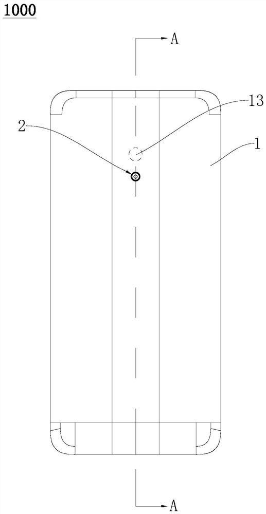
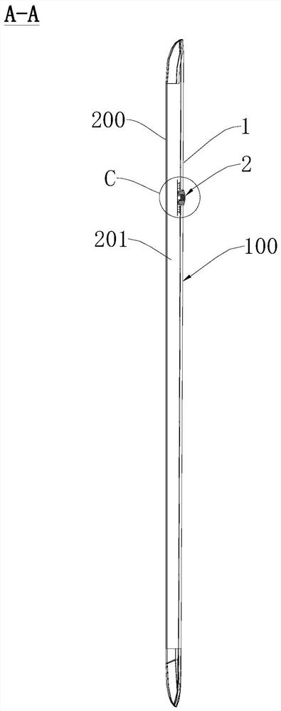
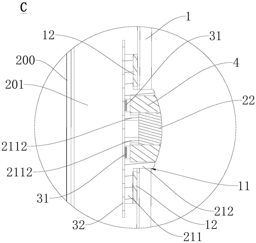
[0026] Refer below Figure 1-Figure 9 An electronic device 1000 according to an embodiment of the present application is described.

[0027] refer to Figure 1-Figure 9 , according to the electronic device 1000 of the embodiment of the present application, the electronic device 1000 includes a housing 1 , a camera, a wear-resistant component 2 and a flash module 3 . The casing 1 includes a light-transmitting portion 13 , and a portion of the casing 1 excluding the light-transmitting portion 13 is formed with a mounting hol...


PUM


Abstract

The invention provides electronic equipment, which comprises a shell body, a camera, an anti-abrasion part and a flash lamp module, wherein the shell body comprises a light-transmitting part, and a mounting hole is formed in the part, except the light-transmitting hole, of the shell body; the camera is arranged on the inner side of the shell body; the anti-abrasion part comprises an installation support and an anti-abrasion block, the anti-abrasion block is arranged on the installation support, the installation support is matched with the installation hole and connected with the shell body, the anti-abrasion block is located in the installation hole, and one part of the anti-abrasion block protrudes out of the outer surface of the shell body so as to protect the light-transmitting part; and the flash lamp module is arranged on the installation support, and a light through hole for light emitted by a flash lamp to penetrate through is defined between the installation support and the anti-abrasion block. According to the electronic equipment, the anti-abrasion block and the flash lamp module are both arranged on the mounting bracket, so that the structure combination of the flash lamp module and the anti-abrasion block is realized, the internal space of the whole machine occupied by the flash lamp module and the anti-abrasion block is reduced, the electronic equipment is convenient to mount, and the appearance expression of the electronic equipment is improved.

Description

technical field [0001] The present application relates to the field of electronic equipment, in particular to an electronic equipment. Background technique [0002] In related technologies, there are mainly two ways to combine the anti-wear point on the back of the casing of mobile phones and other terminal devices and the flashlight: one is that the flashlight is hidden inside the device through a lifting mechanism, and the anti-wear point is independently on the back of the casing. The design makes it necessary to open the lifting mechanism to use the flash, and the flash is easily blocked, which affects the shooting effect. The lifting mechanism takes up a lot of space and costs a lot; The design takes up a lot of space, which is not conducive to the structural design of the whole machine. Contents of the invention [0003] This application proposes an electronic device, which realizes the structural combination of the flashlight module and the wear-resistant block, re...

Claims


Application Information

Patent Timeline
Patent Type & Authority Applications(China)
IPC IPC(8): H04M1/02H04M1/18H04M1/22
CPCH04M1/0264H04M1/0266H04M1/0283H04M1/18H04M1/22
Inventor 赵涵
Owner OPPO CHONGQING INTELLIGENT TECH CO LTD
Why Eureka
Try Eureka