
Rear locking structure with remote unlocking function

A locking structure and rear locking technology, applied in the application field of slide rails, can solve the problems of enlarged space, inconvenience and unwiseness, and achieve the effects of convenient and reliable operation, good practicability and convenient operation.

Active Publication Date: 2021-03-23
ASIA PACIFIC CISWUXICO LTD
View PDF17 Cites 2 Cited by
  • Summary
  • Abstract
  • Description
  • Claims
  • Application Information

AI Technical Summary

Problems solved by technology

[0003] With the increase of server capacity, the cabinet becomes longer, which makes the space required for disassembly and assembly of the server larger. The space reserved for daily use in the existing computer room cannot meet the disassembly and assembly of the server after the capacity is increased, and there is not enough space. Unlocking and removing the server from the slide rails makes it very inconvenient to maintain the server; however, it is unwise to increase the space in the computer room just to disassemble and assemble the server, which will lead to a decrease in space utilization; on the other hand, When removing the server from the middle rail along with the inner rail, due to the length of the cabinet, the user's hands are not long enough, and two people need to work together to unlock the front lock between the middle rail and the inner rail, which is very inconvenient

Method used


Image

  • Rear locking structure with remote unlocking function
  • Rear locking structure with remote unlocking function
  • Rear locking structure with remote unlocking function

Examples


Embodiment Construction

[0031] The specific implementation manner of the present invention will be described below in conjunction with the accompanying drawings.

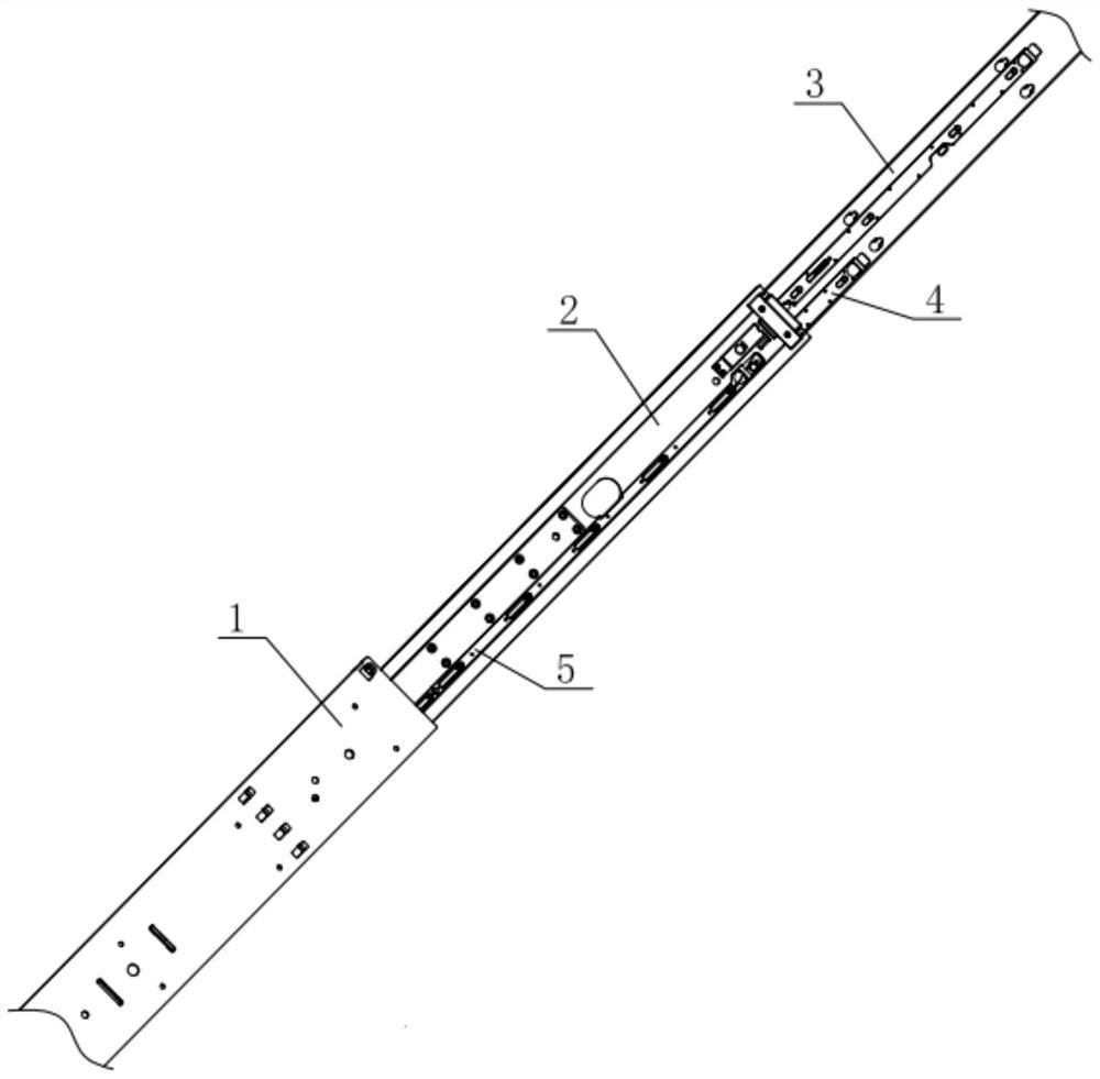
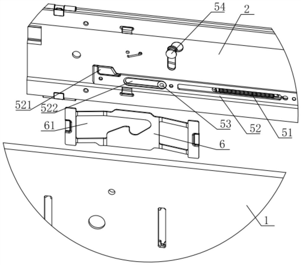
[0032] Such as figure 1 with figure 2 As shown, the remote unlocking rear locking structure of this embodiment includes a middle rail assembly 2 and an outer rail assembly 1 that are relatively slidably connected along the length direction, and a rear Lock assembly 5; pull the pull rod 1 52 along the length direction to unlock the rear lock assembly 5 so that the middle rail assembly 2 slides backward relative to the outer rail assembly 1; structure, the rear end of the middle rail assembly 2 that slides backward is locked by the locking structure at the rear end of the outer rail assembly 1 .

[0033] In a computer room with limited space, first slide out the three rails and lock each other, then unlock the rear lock assembly 5 so that the middle rail assembly 2 slides into the outer rail assembly 1 and lock, leave enough space in fron...


PUM


Abstract

The invention relates to a rear locking structure with a remote unlocking function. The rear locking structure withwith the remote unlocking function comprises a middle rail assembly and an outer railassembly which are in relative sliding connection in the length direction; a rear locking assembly is installed between the front end of the middle rail assembly and the front end of the outer rail assembly; a first pull rod is pulled in the length direction to unlock the rear locking assembly, so that the middle rail assembly slides backwards relative to the outer rail assembly; a locking structure is arranged on the side face, facing the middle rail assembly, of the rear end of the outer rail assembly; the rear end, sliding backwards, of the middle rail assembly is locked by the locking structure at the rear end of the outer rail assembly. In a machine room with limited space, three sliding rails slide out and are locked, then the rear locking assembly is unlocked to enable the middle rail assembly to slide into the outer rail assembly, the middle rail assembly is locked relative to the rear end of the outer rail assembly through the locking structure, so that enough space is reserved in front of the middle rail assembly; the front lock assembly is unlocked to enable an inner rail assembly to completely slide out, and therefore, a server is disassembled. With the rear locking structure of the invention adopted, the problem that the server cannot be smoothly disassembled and maintained in a limited space is solved. The remote unlocking rear locking structure is good in practicability, is convenient to operate and reliable.

Description

technical field [0001] The invention relates to the technical field of slide rail application, in particular to a remote unlocking lock structure. Background technique [0002] The server is usually installed in a cabinet, and matching slide rails are provided in the cabinet, so as to facilitate operations such as exporting and importing the server relative to the cabinet for maintenance. [0003] With the increase of server capacity, the cabinet becomes longer, which makes the space required for disassembly and assembly of the server larger. The space reserved for daily use in the existing computer room cannot meet the disassembly and assembly of the server after the capacity is increased, and there is not enough space. Unlocking and removing the server from the slide rails makes it very inconvenient to maintain the server; however, it is unwise to increase the space in the computer room just to disassemble and assemble the server, which will lead to a decrease in space uti...

Claims


Application Information

Patent Timeline
IPC IPC(8): H05K7/18
CPCH05K7/18
Inventor 于其庞升
Owner ASIA PACIFIC CISWUXICO LTD
Learn More