
Measuring resistor and corresponding measuring method

a resistor and resistor technology, applied in the field of measuring resistors, can solve problems such as errors in the calculation of electric current, and achieve the effect of improving the modeling of spatial variations in current density and good measurement-based correction

Active Publication Date: 2018-12-11
ISABELLENHUTTE HEUSLER
View PDF13 Cites 1 Cited by
  • Summary
  • Abstract
  • Description
  • Claims
  • Application Information

AI Technical Summary

Benefits of technology

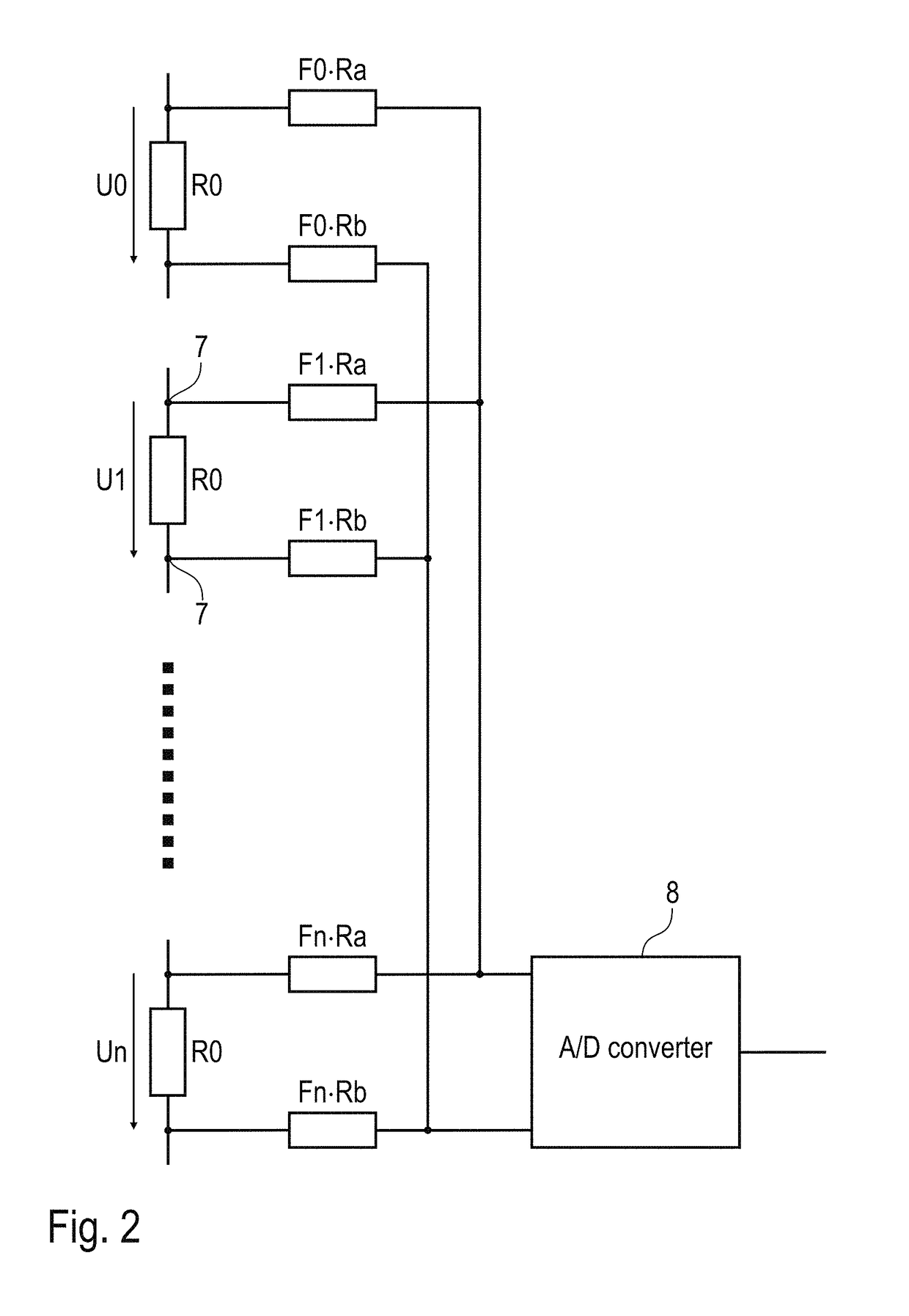
The patent text describes a method for measuring voltage in a resistor with high accuracy. The method involves arranging voltage-measuring contacts in a way that allows for a meaningful representation of the current density distribution. It also suggests using multiple pairs of voltage-measuring contacts to improve the accuracy of the measurements. The weighting factors used to correct for errors in the current density distribution can be determined based on the current measurement parameters. The method also involves synchronous and parallel measurement of multiple voltage values, which reduces noise and improves measurement resolution. Overall, the method provides a reliable and accurate way to measure voltage in a resistor.

Problems solved by technology

In fact, the aforementioned inhomogeneities introduce errors into the calculation of the electric current flowing through the current sense resistor.

Method used


Image

  • Measuring resistor and corresponding measuring method
  • Measuring resistor and corresponding measuring method
  • Measuring resistor and corresponding measuring method

Examples


Embodiment Construction

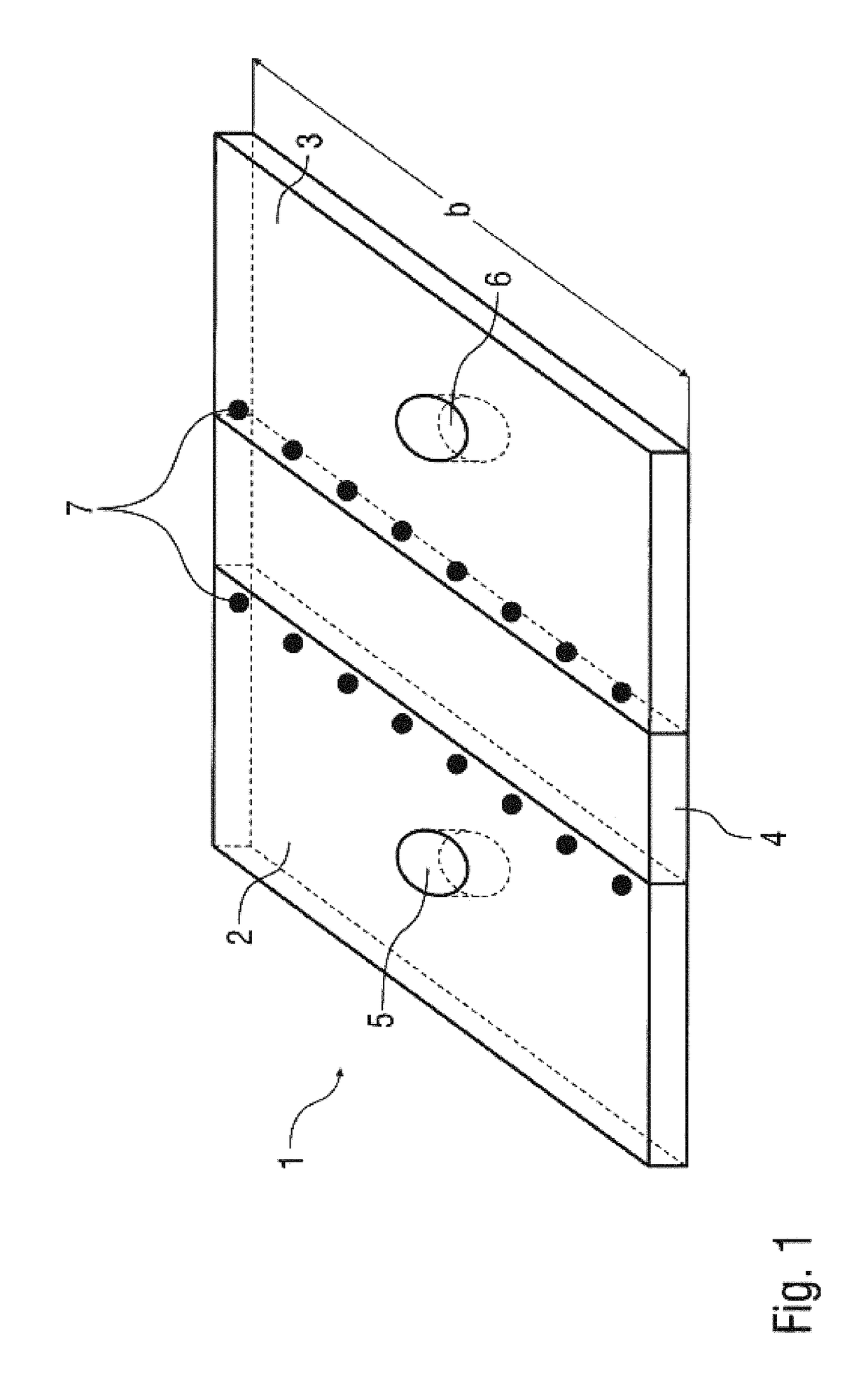
[0045]FIG. 1 shows a planar current sense resistor 1 for measuring current in accordance with the known four-wire technique. The current sense resistor 1 has a mainly conventional design, so additional reference is made to patent application EP 0 605 800 A1, the content of which can therefore be incorporated in full in the present description.

[0046]The current sense resistor 1 essentially comprises two planar connection parts made of a conductive material (e.g. copper or a copper alloy) and a resistor element 4 which is likewise planar and is made of a low-resistance resistive material (e.g. Manganin®). The electric current to be measured is here fed into the connection part 2 then flows through the resistor element 4 and then exits the current sense resistor via the other connection part 3.

[0047]For conducting the electric current in and out, the connection parts 2, 3 each have one or more holes 5, 6, to which connecting contacts, for example, can be screw-fastened.

[0048]In this ex...


PUM


Abstract

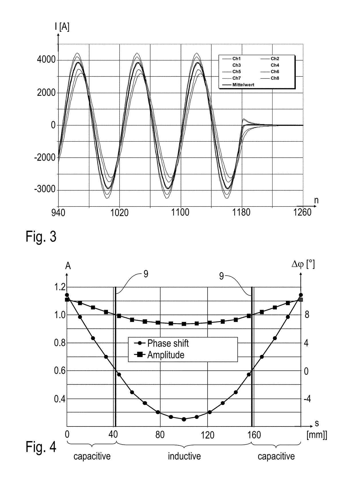
The invention relates to a measuring resistor (1), in particular a low-resistance current-measuring resistor, comprising two terminal parts (2, 3) that consist of a conductor material for introducing and discharging a current, and a resistor element (4) that consists of a resistor material, wherein the resistor element (4) is arranged between the two terminal parts (2, 3) in the direction of the current and current flows through the resistor element (4). According to one variant of the invention, the measuring resistor (1) has several pairs of voltage-measuring contacts (7) for measuring the voltage falling across the resistor element (4) in order to be able to compensate metrologically for inhomogeneities in the current density. In contrast, according to another variant of the invention, one pair of voltage-measuring contacts (7) is arranged at a location at which the measuring resistor (1) exhibits neither a capacitive behavior nor an inductive behavior, such that the current flowing through the measuring resistor (1) and the voltage across the voltage-measuring contacts (7) are substantially in phase.

Description

BACKGROUND OF THE INVENTION[0001]The invention relates to a measuring resistor, in particular a low-resistance current sense resistor. The invention also relates to a corresponding measuring method.[0002]It has been known for some years from the prior art (e.g. DE 42 43 349 A1) to use low-resistance current sense resistors (“shunts”) to measure current by what is known as the four-wire technique. In this technique, the electric current to be measured is fed into the low-resistance current sense resistor, and the voltage drop across the resistor element of the low-resistance current sense resistor is measured. According to Ohm's law, the measured voltage is then a measure of the electric current flowing through the current sense resistor.[0003]Such current sense resistors can have a planar design, such as is described in EP 0 605 800 A1 and DE 42 43 349 A1 for example. WO 2007 / 068409 A1 and DE 10 2005 059 561 A1, for example, describe a different design for such current sense resisto...

Claims


Application Information

Patent Timeline
Patent Type & Authority Patents(United States)
IPC IPC(8): G01R19/00G01R35/00G01R1/20
CPCG01R19/0092G01R35/005G01R1/203A45C1/02A45C2001/022A45F5/02H01C1/14H01C1/144H01C1/148
Inventor HETZLER, ULLRICH
Owner ISABELLENHUTTE HEUSLER
Learn More