Straw picking-up fine powder throwing returning machine

A fine powder and frame technology, applied in loaders, harvesters, crop processors, etc., can solve problems such as difficult natural decay, easy to produce a large number of pests in planting, and unsatisfactory crushing effects, etc.

Pending Publication Date: 2021-03-26
丹东金伟实业有限公司
View PDF0 Cites 0 Cited by
  • Summary
  • Abstract
  • Description
  • Claims
  • Application Information

AI Technical Summary

Problems solved by technology

[0005] In the above-mentioned prior art, since a plurality of rotating blades distributed in the axial direction are used to rotary cut and crush the straw scattered on the field, the crushing effect is not ideal. About 10cm accounted for the maj

Method used


Image

  • Straw picking-up fine powder throwing returning machine
  • Straw picking-up fine powder throwing returning machine
  • Straw picking-up fine powder throwing returning machine

Examples


Embodiment Construction

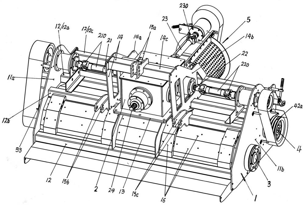
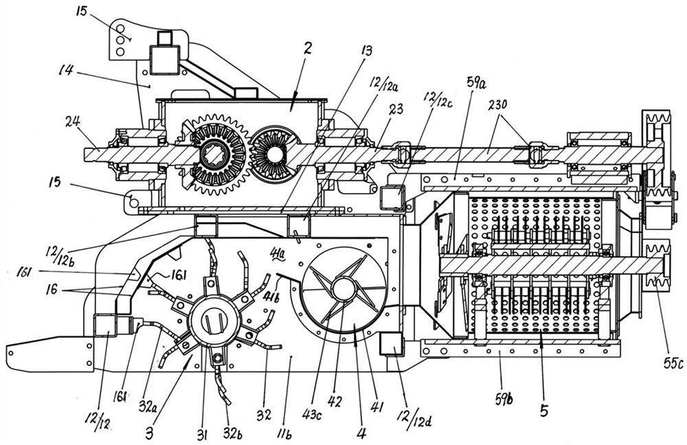
[0021] The machine for picking up fine powder of straw and throwing and returning to the field of the present invention is composed of a frame 1, a gearbox 2, a rotary picking and crushing knife roller device 3, a straw auger pushing roller device 4, and a cylindrical sieve type guillotine cutting and crushing device 5.

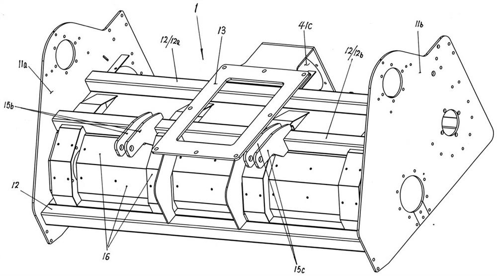
[0022] The frame 1 includes a left frame plate 11a, a right frame plate 11b, a plurality of beam frame rods 12, a gearbox installation base 13, a lifting lug frame 14, an upper lug 15a, a left lug 15b, a right lug 15c, and a cover 16; The left frame plate 11a and the right frame plate 11b are fixedly connected to the left and right ends of the beam frame rod 12, the gearbox mounting base 13 is fixedly installed on the middle part of the upper beam frame rods 12a, 12b, and the gearbox 2 is fixedly mounted on the gearbox mounting base 13 on;

[0023] Hanger frame 14 is made of left vertical plate 14a, right vertical plate 14b, beam bar 14c, and left vertical pl...


PUM


Abstract

The invention provides a picking-up fine powder returning machine. The picking-up fine powder returning machine is mainly characterized by being composed of a machine frame, a gearbox, a rotary picking and smashing knife roll device, a straw auger pushing roll device and a cylinder screen type chopping and smashing device; and straws are fully crushed into fine powder and returned to the field, sothat the straws are rotted more quickly, and the operation of a spring cultivator is facilitated.

Description

technical field [0001] The invention relates to agricultural machinery, in particular to a machine for picking up, crushing and returning corn stalks. Background technique [0002] After the corn cobs are harvested by the corn harvester, the corn stalks are smashed and scattered on the field. In order to return the corn stalks to the field, the straw crushing and returning machine is used to further crush the corn stalks and return them to the field. [0003] There are many kinds of corn stalk crushing and returning machines in the prior art, with different specific structures and different effects. However, the stalks scattered on the field are all rotary-cut, impacted and pulverized with a plurality of rotating blades distributed in the axial direction. [0004] CN2020108507298 discloses a two-axis corn stalk crushing and returning machine, which is mainly composed of a rake rake installed in the casing, a first crushing knife roller, and a second crushing knife roller, a...

Claims


Application Information

Patent Timeline
IPC IPC(8): A01D82/00A01D82/02A01D89/00
CPCA01D82/00A01D82/02A01D89/001A01D89/002
Inventor 杨镇名
Owner 丹东金伟实业有限公司
Why Eureka
Try Eureka