

ratchet wrench
A technology of ratchet wrench and ratchet, which is applied in the field of ratchet wrench, which can solve the problems of reducing gear teeth, construction of wrench in narrow space, limitation, etc., and achieve the effect of reducing the swing angle
- Summary
- Abstract
- Description
- Claims
- Application Information
AI Technical Summary
Problems solved by technology
Method used
Image

Examples
Embodiment Construction
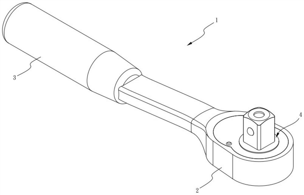
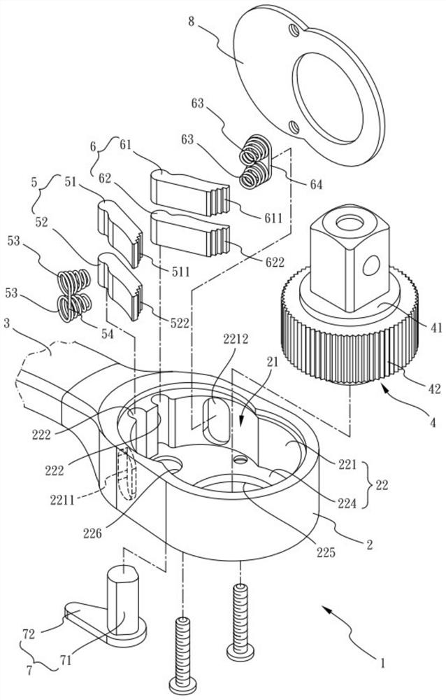
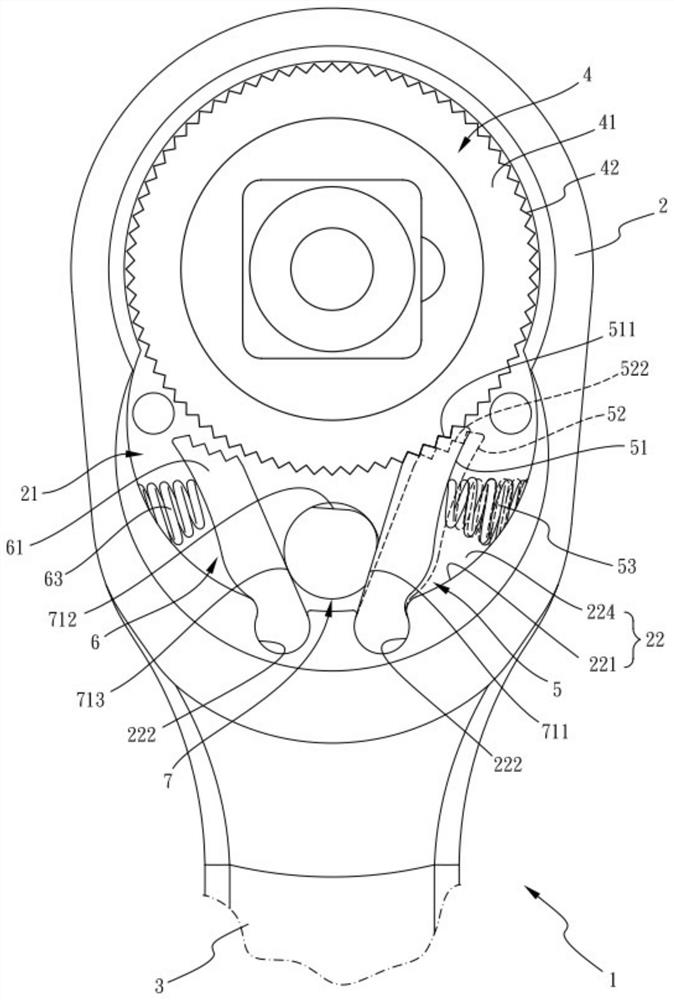
[0066] The present embodiment takes the type of ratchet having a sleeve linking part as an example, e.g., Figures 1 through 2Is a ratchet wrench, which comprises: a body 1, its opposite end is a head 2 and a handlebar 3, the head 2 has a displacement groove 21, the capacitive groove 21 additionally runs through a wheel axle perforation 225 and a reversing piercing 226; a ratchet 4, the ratchet 4 has a wheel part 41, the ratchet 4 pivot is located in the head 2 axle perforation 225, the wheel part 41 is located inside the container 21, the wheel part 41 side ring is provided with several wheel teeth 52; a forward puller group 5, It is located in the tolerance groove 21 and grouped to the capacitive groove 21, the forward actuation group 5 includes a first actuator 51 and a second actuator 52, the first actuator 51 one end set is disposed in the capacity slot 21 and the other end having a plurality of gear teeth 42 of the several first bite teeth 511, the second actuation block 52 o...
PUM
 Abstract
Description
Claims
Application Information