A Noise Removal Method for Shaft Wall Image in Deep Shaft

A shaft and shaft technology, applied in the field of image denoising, can solve the problems of high difficulty in denoising, difficulty in evaluating the level and type of noise, and achieve the effect of retaining feature information

Active Publication Date: 2022-05-27
ANHUI UNIV OF SCI & TECH
View PDF7 Cites 0 Cited by
  • Summary
  • Abstract
  • Description
  • Claims
  • Application Information

AI Technical Summary

Problems solved by technology

The denoising methods in the existing literature mostly use standard images to test the denoising effect. The noise contained in the actual image is not single, and it is difficult to evaluate the level and type of noise. The difficulty of denoising is much higher than removing the known noise added to the standard image. noise

Method used


Image

  • A Noise Removal Method for Shaft Wall Image in Deep Shaft
  • A Noise Removal Method for Shaft Wall Image in Deep Shaft
  • A Noise Removal Method for Shaft Wall Image in Deep Shaft

Examples


Embodiment Construction

[0046]The technical solutions in the embodiments of the present invention will be clearly and completely described below with reference to the accompanying drawings in the embodiments of the present invention. Obviously, the described embodiments are only a part of the embodiments of the present invention, rather than all the embodiments. Based on the embodiments of the present invention, all other embodiments obtained by those of ordinary skill in the art without creative efforts shall fall within the protection scope of the present invention.

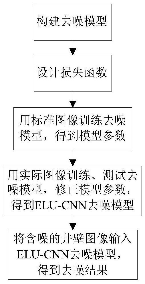
[0047] like figure 1 As shown, the present invention discloses a method for denoising a deep shaft wall image, which includes five steps. Step 1, construct the denoising model; Step 2, design the loss function; Step 3, train the denoising model with standard images to obtain model parameters; CNN denoising model; Step 5, input the noisy borehole wall image into the ELU-CNN denoising model to obtain the denoising result.

[0048] Fur...


PUM


Abstract

The invention discloses a method for denoising images of shaft walls of deep shafts, comprising five steps: Step 1, constructing a denoising model; Step 2, designing a loss function; Step 3, using standard images to train the denoising model to obtain model parameters; Step 4 , use the actual image to train and test the denoising model, modify the model parameters, and obtain the ELU-CNN denoising model; Step 5, input the noisy well wall image into the ELU-CNN denoising model to obtain the denoising result. The denoising model is 28 layers deep, including 5 feature extraction modules FEM and skip links. The skip links combine the output features of the first convolutional layer with the output features of each FEM in series, so that the low-level features extracted by the first layer are continuously used. , to ensure the full extraction of image features. The invention can well preserve the texture features of the damaged part of the well wall when removing the blind noise of the well wall image.

Description

technical field [0001] The invention relates to the field of image denoising, in particular to a method for denoising images of a deep shaft wall. Background technique [0002] About 2.95 trillion tons of coal resources in my country are buried below 1000m, accounting for 53% of the total coal resources. With the continuous development of social economy, a large number of coal mines in China have been transferred to deep mining in the 21st century. The high temperature and high humidity environment of deep wells and the erosion of saline-alkali water will slowly corrode the wellbore wall concrete. The annular pressure caused by the expansion of magma and mud around the wellbore that the wellbore bears will cause damage such as bursting and bulging on the wellbore. The damage must be detected and repaired in time to effectively ensure the safety of the wellbore and prevent the occurrence of well wall rupture. [0003] Images are an important means for humans to acquire, ex...

Claims


Application Information

Patent Timeline
Patent Type & Authority Patents(China)
IPC IPC(8): G06T5/00G06T5/20
Inventor 贾晓芬柴华荣郭永存黄友锐赵佰亭
Owner ANHUI UNIV OF SCI & TECH
Why Eureka
Try Eureka