Connector assembly

A technology of assembly and connector, applied in the direction of connection, parts and instruments of connecting device, etc., can solve the problem of inability to connect with plug and terminal

Active Publication Date: 2021-02-02
HIROSE ELECTRIC GROUP
View PDF9 Cites 0 Cited by
  • Summary
  • Abstract
  • Description
  • Claims
  • Application Information

AI Technical Summary

Problems solved by technology

That is, it is not possible to wire the paired plug terminals to the driving device under the same conditions

Method used


Image

  • Connector assembly
  • Connector assembly
  • Connector assembly

Examples


Embodiment Construction

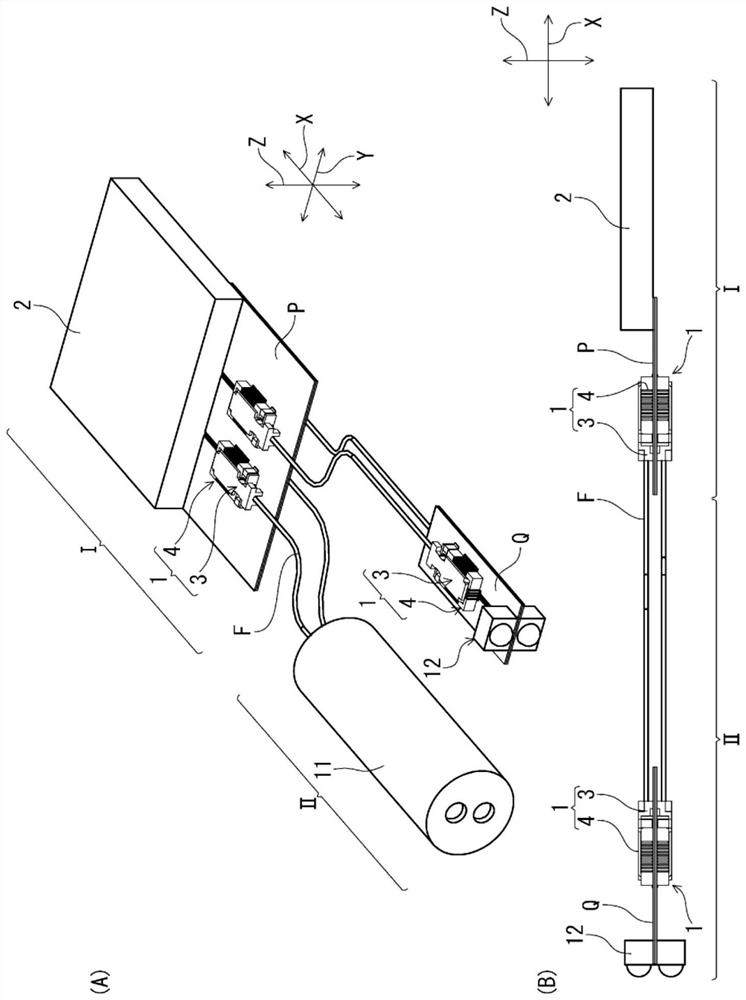
[0028] figure 1 (A) is a perspective view showing a state in which a connector assembly according to an embodiment of the present invention is installed in a signal processing unit housed in an electronic device (not shown) and a measurement unit extending from the electronic device, figure 1 (B) is its side view.

[0029] exist figure 1 In (A) and (B), the signal processing unit I housed in the electronic device and the measurement unit II extending from the electronic device are shown. The electronic device and the measurement unit II constitute, for example, an endoscope system. In this case, the electronic device forms a main body of the endoscope system, and the measurement unit II forms an endoscope.

[0030] The signal processing unit I is configured to convert the optical signal received from the measuring unit II through the optical fiber cable F into an electronic signal, and process it. A plurality of connector assemblies 1 for conversion, and a processor 2 as a ...


PUM


Abstract

The invention provides a connector assembly capable of connecting a pair of terminals arranged in the same column to a driving device with the same connection length to form a signal transmission pathwith the same condition. The connector assembly (1) is provided with: a plug connector (3) having built therein a photoelectric conversion element (20) capable of converting an optical signal and anelectrical signal from one side to the other side, and a drive device (21) for driving the photoelectric conversion element; and a receptacle connector (4) into which the plug connector is fitted, theplug connector and the receptacle connector being electrically connected by contact of terminals of each other, and for the plug connector, the front end side of an optical fiber cable (F) for transmitting an optical signal is connected to the rear end side of the plug connector and extends and protrudes rearward. Side terminals (51) are respectively arranged on a pair of side edge parts (33) extending in the front-rear direction (X), and end terminals (52) are arranged on a front end edge part (34) extending perpendicularly to the front-rear direction (X).

Description

technical field [0001] The present invention relates to a connector assembly including a plug connector capable of converting an optical signal and an electrical signal from one to the other, and a receptacle connector into which the plug connector is fitted. Background technique [0002] Such a connector assembly is disclosed in Patent Document 1, for example. In Patent Document 1, with respect to the plug connector ("connector 1" in Patent Document 1), the optical fiber cable used for optical signal transmission is connected so as to extend and protrude from the plug connector in one direction (rearward). The optical signal transmitted by the above-mentioned optical fiber cable is converted into an electric signal by a light-receiving element as a photoelectric conversion element built in the above-mentioned plug connector. In this plug connector, in addition to the photoelectric conversion element described above, a driving device for driving the photoelectric conversion...

Claims


Application Information

Patent Timeline
IPC IPC(8): G02B6/42H01R12/71
CPCG02B6/4274G02B6/4279H01R12/716H01R12/7082H01R12/75H01R12/83G02B6/4284G02B6/428G02B6/4214G02B6/4261H01R13/665G02B6/4278H01R13/6273
Inventor 石田成纪后藤雅之佐野义昭
Owner HIROSE ELECTRIC GROUP
Why Eureka
Try Eureka