Plastic square piece block mark branding equipment
A branding and piece technology, which is applied in the field of plastic square piece mark branding equipment, can solve the problems that the branding piece is easy to stick to the plastic square piece, unfavorable environmental protection, and harm to workers' bodies, etc., so as to achieve environmental protection, The effect of reducing contact and ensuring safety
- Summary
- Abstract
- Description
- Claims
- Application Information
AI Technical Summary
Problems solved by technology
Method used
Image
Examples
Embodiment 1
[0063] A plastic square block logo branding equipment, such as figure 1 As shown, it includes a bottom plate 1, a support seat 2, a worktable 3 and a branding mechanism 4. The front and rear sides of the bottom plate 1 are provided with a support seat 2, and a workbench 3 is arranged between the tops of the two support seats 2. The workbench 3 There is a branding mechanism 4 on it.
[0064] When it is necessary to carry out logo branding to the plastic square block, the plastic square block is first placed under the branding mechanism 4, and then people rotate the branding mechanism 4, so that the branding mechanism 4 moves downward to carry out logo branding on the plastic square block below, loosen Open the branding mechanism 4, so that the branding mechanism 4 moves upwards without force and resets, and people take off the plastic square block that has been branded afterwards and cool it down, and repeat the above-mentioned operations when using it again.
Embodiment 2
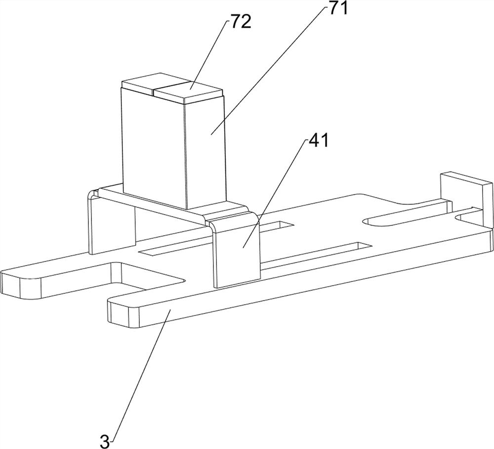
[0066] On the basis of Example 1, such as figure 2 and image 3As shown, the branding mechanism 4 includes an upper support plate 41, a support column 42, a linkage plate 43, a branding plate 44, a first compression spring 45, a wedge block 46 with a column, a fixed baffle 47, a rotating push column 48 and a torsion spring 49. An upper support plate 41 is provided on the left side of the top of the workbench 3, and support columns 42 are provided on the front and rear sides of the bottom of the upper support plate 41. The two support columns 42 are connected to the workbench 3. Between the upper parts of the two support columns 42 The sliding type is provided with a linkage plate 43, the middle side of the bottom of the linkage plate 43 is provided with a branding plate 44, and the lower parts of the two support columns 42 are covered with a first compression spring 45, and the first compression spring 45 is respectively linked with the support column 42 and The plates 43 ar...
Embodiment 3
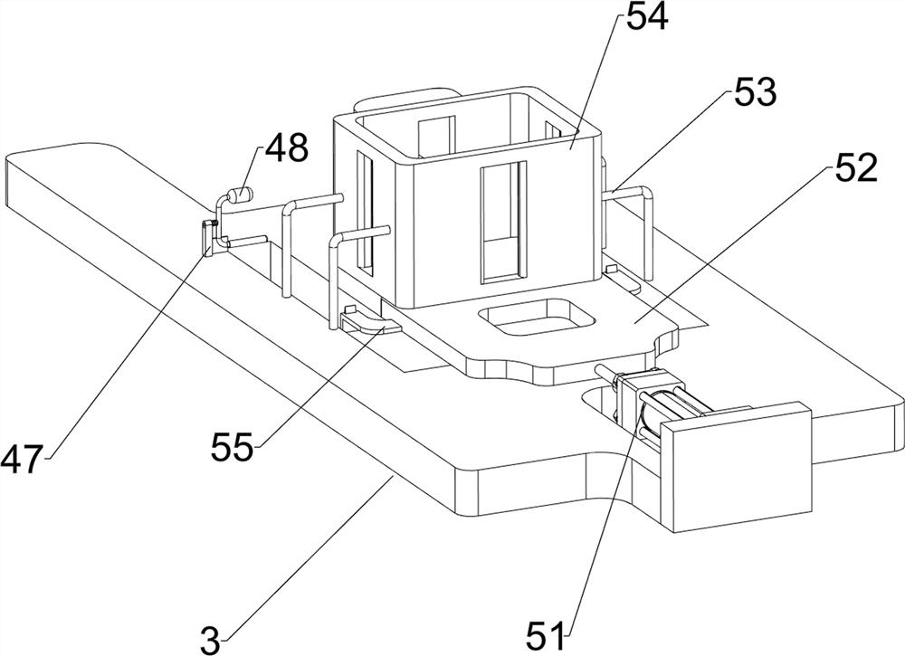
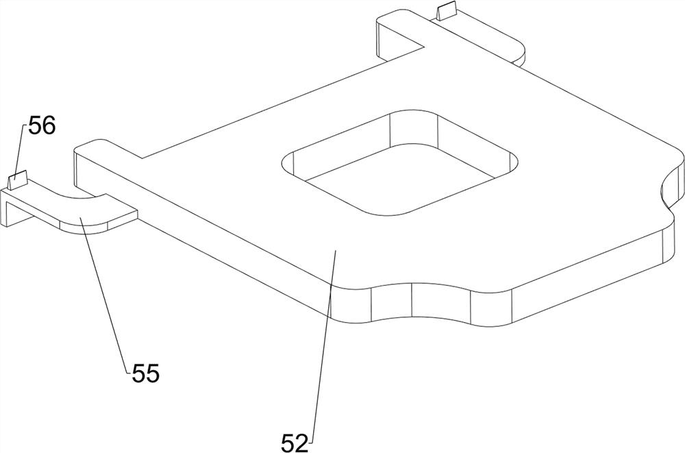
[0069] On the basis of Example 2, such as figure 1 , Figure 4 , Figure 5 , Image 6 , Figure 7 , Figure 8 , Figure 9 with Figure 10 As shown, it also includes a blanking mechanism 5, a material retaining mechanism 6, a purification mechanism 7 and a water cooling mechanism 8, the workbench 3 is provided with a blanking mechanism 5, and the upper support plate 41 is provided with a material retaining mechanism 6 and a purification mechanism 7. The bottom plate 1 is provided with a water cooling mechanism 8 .
[0070] The unloading mechanism 5 can be used for continuous unloading. First, put a certain amount of plastic squares into the unloading mechanism 5, and then start the unloading mechanism 5. The unloading mechanism 5 moves to the left, and then sends the material to the imprinting plate. 44, then the blanking mechanism 5 moves to the right and resets, and simultaneously drives the branding mechanism 4 to move downwards, and then carries out the mark branding...
PUM
 Abstract
Description
Claims
Application Information
 - R&D
- Intellectual Property
- Life Sciences
- Materials
- Tech Scout
- Unparalleled Data Quality
- Higher Quality Content
- 60% Fewer Hallucinations
Browse by: Latest US Patents, China's latest patents, Technical Efficacy Thesaurus, Application Domain, Technology Topic, Popular Technical Reports.
© 2025 PatSnap. All rights reserved.Legal|Privacy policy|Modern Slavery Act Transparency Statement|Sitemap|About US| Contact US: help@patsnap.com


