Three-dimensional mould with lifting degree for sewing shoes and boots and sewing method for pressing toe part on heel part

A front-end, three-dimensional technology, applied in sewing equipment, sewing machine components, textiles and papermaking, etc., can solve the problems that the sewing effect cannot meet the requirements of the process, the work efficiency is low, and the intelligent automation equipment cannot be used, so as to improve production. Effect of skill level

Pending Publication Date: 2021-03-26
JIHUA 3513 IND
View PDF0 Cites 0 Cited by
  • Summary
  • Abstract
  • Description
  • Claims
  • Application Information

AI Technical Summary

Problems solved by technology

[0002] When the front of the shoe is pressed against the back of the shoe, because the back has been formed, it is not in a flat structure, and there is still a sway, so it is impossible to use intelligent automation equipment. It can only be operated manually by a sewing machine, but when sewing curved When the camber is large, the sewing effect cannot meet the requirements of the process, and an operator with sewing experience must be required to sew, and the work efficiency is low.

Method used


Image

  • Three-dimensional mould with lifting degree for sewing shoes and boots and sewing method for pressing toe part on heel part
  • Three-dimensional mould with lifting degree for sewing shoes and boots and sewing method for pressing toe part on heel part
  • Three-dimensional mould with lifting degree for sewing shoes and boots and sewing method for pressing toe part on heel part

Examples


Embodiment 1

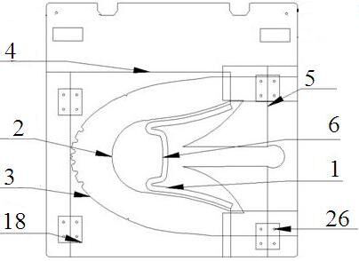
[0036] This embodiment provides a three-dimensional mold with sway for sewing shoes and boots, including a bottom plate 1, a rear upper limiting plate 2, a front upper limiting plate 3, a front upper pressing plate 4 and a rear upper three-dimensional separation pressing plate 5. The bottom plate 1 is provided with a wire groove 6, and the three-dimensional separation pressing plate 5 of the rear side forms a sway;

[0037] The bottom plate 1, the rear side limiting plate 2, the front side limiting plate 3, the front side pressing plate 4 and the rear side three-dimensional separation pressing plate 5 are arranged in sequence from bottom to top and the wire groove 6 is exposed in the middle, and the rear side limiting plate 2 It is fixedly connected with the bottom plate 1, the front side limiting plate 3 is connected to the left side of the rear side limiting plate 2, the front side pressure plate 4 is hinged to the left side of the front side limiting plate 3, and the rear si...

Embodiment 2

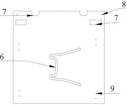
[0040] On the basis of Embodiment 1, this embodiment provides a three-dimensional mold with sway for sewing shoes and boots. The two sides of the upper end of the bottom plate 1 are symmetrically opened with a quick-change card slot-7 and a positioning hole-8. A plurality of hinge positioning holes 9 are arranged symmetrically on both sides of the bottom plate 1 .

[0041] Such as figure 2 As shown, the quick-change clamp of the pattern machine can clamp the three-dimensional mold through the quick-change card slot 7, thereby ensuring that the three-dimensional mold will not move. Positioning hole one 8 is used for positioning up and down, and hinge positioning hole one 9 is used for the calibration positioning of the front side limiting plate 3 and the back side limiting plate 2 bonding.

Embodiment 3

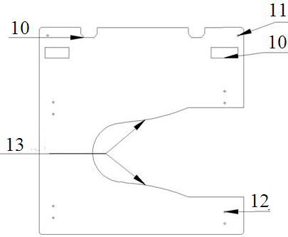
[0043] On the basis of Embodiment 1, this embodiment provides a three-dimensional mold with sway for sewing shoes and boots. The two sides of the upper end of the back limit plate 2 are symmetrically opened with two quick-change card slots 10 and two positioning holes. 11. A plurality of hinge positioning holes 12 are arranged symmetrically on both sides of the rear panel limiting plate 2, and the right side of the rear panel limiting plate 2 is open, and the inner edge of the opening forms a rear panel limiting arc 13, so The arc 13 of the back gang limiting arc 13 coincides with the radian that the inner and outer ankles of the back gang need to be pressed by the front gang to make up the sewing position.

[0044] Such as image 3 As shown, the back stop limiting plate 2 is bonded on the base plate 1, and its function is to fix the back sheet to prevent the sheet from shifting. Hinge positioning hole two 12 is used for the calibration positioning of the front side limiting ...


PUM

PropertyMeasurementUnit
Thicknessaaaaaaaaaa
Thicknessaaaaaaaaaa

Abstract

The invention provides a three-dimensional mould with lifting degree for sewing shoes and boots and a sewing method for pressing a toe part on a heel part. The three-dimensional mould comprises a bottom plate, a heel part limiting plate, a toe part limiting plate, a toe part pressing plate and a heel part three-dimensional separation pressing plate; a thread groove is formed in the bottom plate; the heel part three-dimensional separation pressing plate forms the lifting degree; the bottom plate, the heel part limiting plate, the toe part limiting plate, the toe part pressing plate and the heelpart three-dimensional separation pressing plate are arranged from the bottom up in sequence, and the middle parts of the bottom plate, the heel part limiting plate, the toe part limiting plate, thetoe part pressing plate and the heel part three-dimensional separation pressing plate expose the thread groove; the heel part limiting plate is fixedly connected with the bottom plate; the toe part limiting plate is connected with the left side of the heel part limiting plate; the toe part pressing plate is hinged with the left side of the toe part limiting plate; and the heel part three-dimensional separation pressing plate is hinged with the right side of the heel part limiting plate. The technology that a computerized pattern sewing machine can only sew a plane is broken through, and the production efficiency is greatly improved while the product sewing problem is solved; and during sewing, operation can be carried out only by putting a material piece into a designated position, operation can be carried out by an operator who is not familiar with the sewing machine, long-time training is not needed, and the production skill level of the vast number of staff is further improved.

Description

technical field [0001] The invention belongs to the technical field of shoe-making sewing, and in particular relates to a three-dimensional mold with sway for sewing shoes and boots and a method for sewing a front upper and a rear upper. Background technique [0002] When the front of the shoe is pressed against the back of the shoe, because the back has been formed, it is not in a flat structure, and there is still a sway, so it is impossible to use intelligent automation equipment. It can only be operated manually by a sewing machine, but when sewing curved When the position is large, the sewing effect cannot meet the requirements of the process, and an operator with sewing experience must be required to sew, and the work efficiency is low. Contents of the invention [0003] The object of the present invention is to provide a three-dimensional mold with sway for sewing shoes and boots, so as to overcome the above-mentioned technical problems in the prior art. [0004] A...

Claims


Application Information

Patent Timeline
IPC IPC(8): D05B35/00
CPCD05B35/00
Inventor 王骊薛华峰
Owner JIHUA 3513 IND
Why Eureka
Try Eureka