Die for sewing eyelets
A technology of eyelets and molds, applied in footwear, applications, clothing, etc., can solve the problems of affecting the appearance of shoes, high material costs, and reducing the service life of shoes, so as to improve production skills, reduce material costs, and solve sewing problems. problem effect
- Summary
- Abstract
- Description
- Claims
- Application Information
AI Technical Summary
Problems solved by technology
Method used
Image
Examples
Embodiment 1
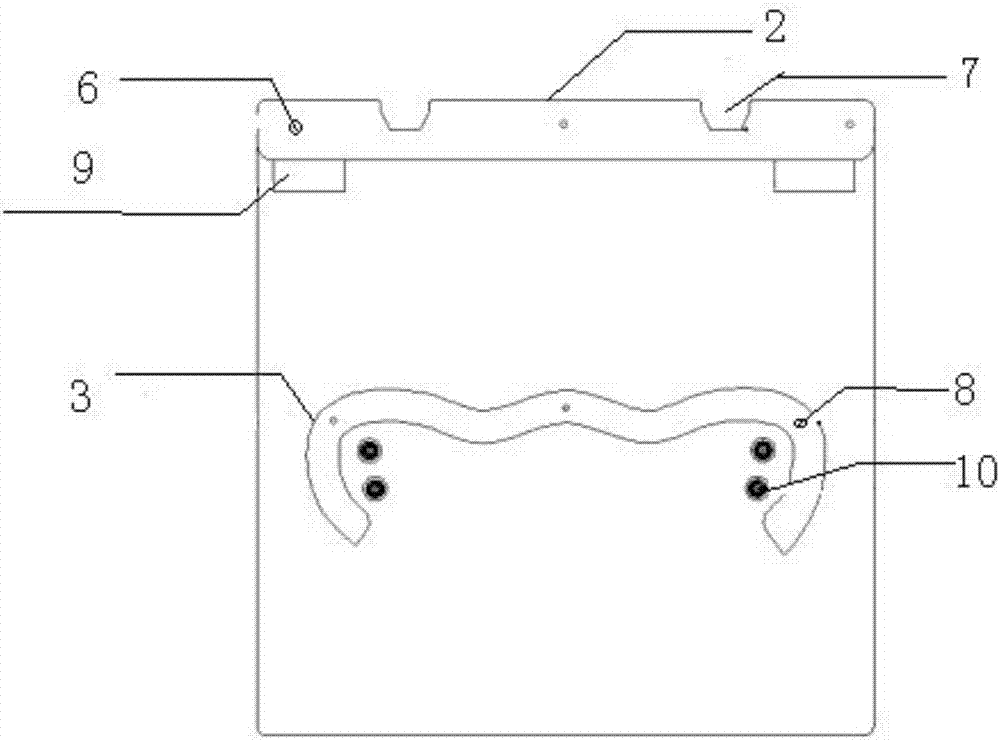
[0019] Such as figure 1 As shown, a mold for sewing eyelets includes a base plate 1, a horizontal bar slot 2 and a limit bar 3, the horizontal bar slot 2 and the limit bar 3 are respectively connected to the top and middle of the bottom plate 1, and the bottom plate 1 There is a wire groove 10, and the wire groove 10 is located under the limit bar 3; this kind of mold for sewing eyelets is fixedly connected with the programmable electronic pattern machine through the horizontal bar card slot 2, and only needs to put the material into the limit bar In the position of the lower edge of 3, the slot 10 is used to align the sewing range of the programmable electronic pattern machine. When the programmable electronic pattern machine is started, the shoe eyelet can be sewn. The material for sewing the shoe eyelet can be silk thread, etc. Arbitrary material, beautiful eyelets, solves the problem that ordinary sewing machines cannot sew the round eyelets, and the cost of materials is l...
Embodiment 2
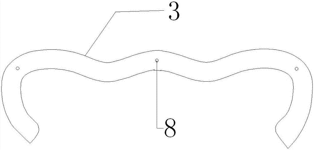
[0021] Such as Figure 1-4 As shown, on the basis of Embodiment 1, a plurality of upper positioning holes 4 and middle positioning holes 5 are respectively opened on the top and the middle of the bottom plate 1, and a plurality of upper positioning holes 4 corresponding to the upper positioning holes 4 are opened on the bar slot 2. Horizontal bar slot positioning hole 6, the limit bar 3 has a limit positioning hole 8 corresponding to the middle positioning hole 5, the upper positioning hole 4 and the horizontal bar slot positioning hole 6, the middle positioning hole 5 and the limit position The position positioning holes 8 are all positioned through the positioning rod; the horizontal bar slot 2 and the limit bar 3 are fixedly connected to the bottom plate 1 through the positioning holes respectively. 3 fixed to the corresponding position, the operation is simple and convenient with high precision.
Embodiment 3
[0023] Such as figure 1 , 3 As shown in and 4, on the basis of Embodiment 1-2, the upper end of the horizontal bar card slot 2 is provided with a quick change slot 7, and the bottom plate 1 below the upper positioning hole 4 is provided with a card slot 9, and the middle positioning hole 5 The base plate 1 below is provided with a wire groove 10, and the quick-change groove 7 and the card groove 9 are used to connect the card board on the programmable electronic pattern machine, and the mold is well fixed on the programmable electronic pattern machine, and the operation is simple and convenient.
PUM
 Abstract
Description
Claims
Application Information
 - R&D
- Intellectual Property
- Life Sciences
- Materials
- Tech Scout
- Unparalleled Data Quality
- Higher Quality Content
- 60% Fewer Hallucinations
Browse by: Latest US Patents, China's latest patents, Technical Efficacy Thesaurus, Application Domain, Technology Topic, Popular Technical Reports.
© 2025 PatSnap. All rights reserved.Legal|Privacy policy|Modern Slavery Act Transparency Statement|Sitemap|About US| Contact US: help@patsnap.com


