
Mining mechanical automatic spraying device

A spray device and mechanical technology, which is applied in safety devices, mining equipment, earthwork drilling, etc., can solve the problems of cumbersomeness, no consideration of reset and spray time, poor working stability, etc., and achieve the reduction of overall volume and effective spray duration The effect of control and reset action stability

Pending Publication Date: 2021-03-26
常熟市通防电器有限公司
View PDF2 Cites 0 Cited by
  • Summary
  • Abstract
  • Description
  • Claims
  • Application Information

AI Technical Summary

Problems solved by technology

Both of them can be stably triggered by impact force and carry out spray and dust reduction during blasting operation, but there are still the following deficiencies: first, the structure of both is relatively loose, resulting in a large volume, which is not conducive to logistics transportation and installation; second , the former uses a lever-type heavy hammer lifting device to reset, which involves many and cumbersome steps in the actual operation process, and some even still need to use the motor to realize the reset operation, and the work stability is poor, while the latter does not consider reset at all. and spraying time, both of which cannot meet the needs of blasting operations

Method used


Image

  • Mining mechanical automatic spraying device
  • Mining mechanical automatic spraying device
  • Mining mechanical automatic spraying device

Examples


Embodiment Construction

[0021] The specific implementation of the present invention will be described in detail below in conjunction with the accompanying drawings, but the description of the embodiments is not a limitation on the technical solution, and any changes in form but not in substance according to the concept of the present invention should be regarded as the protection scope of the present invention.

[0022] In the following descriptions, all concepts involving directionality or orientation of up, down, left, right, front and back are aimed at the current figure 1 As far as the position and state of the present invention are concerned, it cannot be understood as a special limitation on the technical solution provided by the present invention.

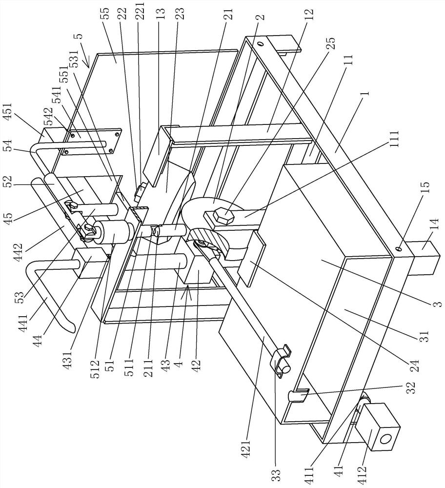
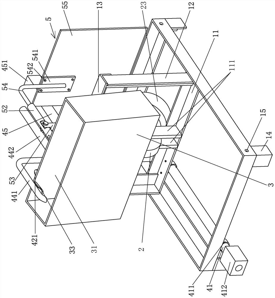
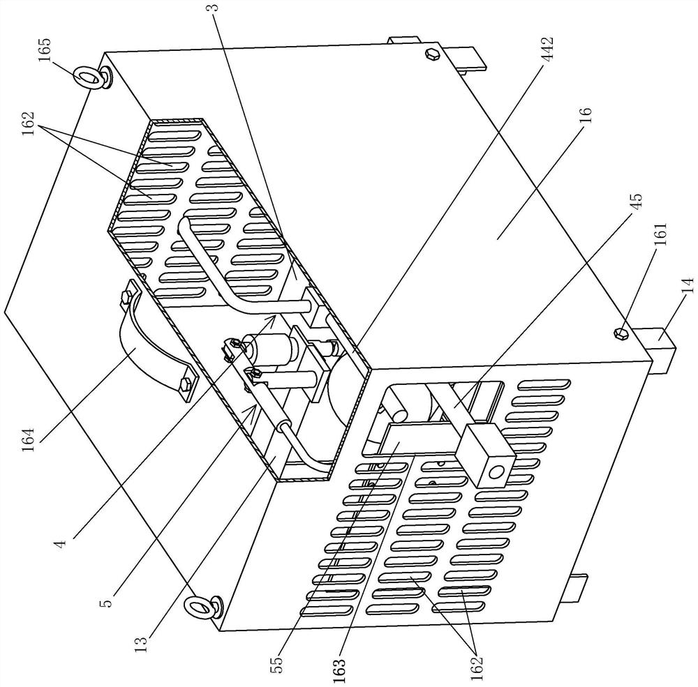
[0023] see Figure 1 to Figure 3 , the present invention relates to a mechanical automatic spraying device for mining, comprising a base 1, a turntable 2 rotatably supported on the base 1, a water tank 3 fixed to the turntable 2 and rotating with t...


PUM


Abstract

Disclosed is a mining mechanical automatic spraying device. The mining mechanical automatic spraying device comprises a base, a rotary disc supported on the base in a rotating mode, a water tank fixedto the rotary disc and rotating along with the rotary disc, a control device fixed to the base and connected with the water tank in a matched mode, and a trigger device matched with the rotary disc.The control device comprises a water inlet pipe fixed to the base, a control valve connected with one end of the water inlet pipe, a connecting pipe connected with the control valve, an adjusting valve connected with the upper end of the connecting pipe and a water outlet pipe arranged in the middle of the connecting pipe and extending backwards, and a control valve rod is arranged on the controlvalve. The control valve rod extends towards one side of the water tank and is movably connected with the water tank; a weeping pipe matched with the water tank is arranged on the side, facing the water tank, of the upper portion of the adjusting valve; a lower locking rod connected with the triggering device is formed upwards on the rotary disc; and a balancing weight is fixed to the position, obliquely upwards on the rear side of the lower locking rod, of the rotary disc. The spraying duration can be effectively controlled, and the reset action is more stable and reliable, and the overall size is small.

Description

technical field [0001] The invention belongs to the technical field of mine dust suppression equipment, and in particular relates to a mine mechanical automatic spraying device. Background technique [0002] Coal mines are the main natural resources of our country. Rational use and exploitation of coal mines is an important part of promoting my country's economic development. However, there are great safety risks in the mining process of coal mines. A slight negligence may cause an explosion to cause the mine to collapse. Explosions caused by excessive dust concentration are relatively common accidents. Among them, blasting is a commonly used coal mining method. It has high mining efficiency and large output, but the amount of dust generated is relatively large. If the dust cannot be suppressed in time, it will be very difficult. There is a risk of explosion. At present, solenoid valves or sensors are often used to control spraying devices in mines to achieve the purpose of...

Claims


Application Information

Patent Timeline
Patent Type & Authority Applications(China)
IPC IPC(8): E21F5/04
CPCE21F5/04
Inventor 周伟刚
Owner 常熟市通防电器有限公司
Features
  • Generate Ideas
  • Intellectual Property
  • Life Sciences
  • Materials
  • Tech Scout
  • Unparalleled Data Quality
  • Higher Quality Content
  • 60% Fewer Hallucinations
Learn More