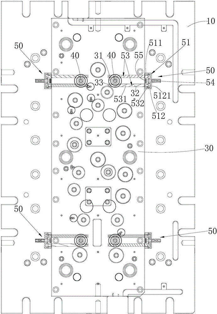
[0026] In order to make the objectives, technical solutions, and advantages of the present invention clearer, the following further describes the present invention in detail with reference to the accompanying drawings and embodiments. It should be understood that the specific embodiments described here are only used to explain the present invention, but not to limit the present invention.
[0027] See Figure 1 to Figure 4 The strong return structure of the ejector plate of the mold provided by the embodiment of the present invention includes a movable mold bottom plate 10 with an ejector hole 11; an injection molding machine ejector rod 20 that can penetrate the ejector hole 11; an ejector pin disposed opposite to the movable mold bottom plate 10 The ejector plate 30 is provided with a mounting hole 31 corresponding to the ejector hole 11; a connector 40 connected to the end of the ejector pin 20 of the injection molding machine facing the ejector plate 30 and inserted in the mounting hole 31; and detachable The ground is connected to the thimble plate 30 and is used to limit the connecting member 40 at the limit mechanism 50 at the mounting hole 31 along the width direction of the thimble plate 30.
[0028] In the upper mold, the end of the ejector rod 20 of the injection molding machine is connected with a connector 40. The mold is moved by a crane, and the connector 40 is pushed into the ejector hole 11 of the movable mold bottom plate 10 and inserted into the mounting hole 31 of the ejector plate 30 , The connecting member 40 is limited to the mounting hole 31 along the width direction of the ejector plate 30 by the limiting mechanism 50, so that the ejector rod 20 and the ejector plate 30 of the injection molding machine are integrated, and the ejector force directly acts on the ejector plate 30 to push The ejector plate 30 is pulled back by the ejector rod 20 of the injection molding machine to provide the pulling force, and the reset action is reliable. When the mold is lowered, the limit mechanism 50 can be disassembled. With the forced return mechanism of the ejector plate 30 of the mold, there is no need to disassemble and assemble the ejector rod 20 of the injection molding machine when the upper and lower molds are used, which is convenient for operation, less time-consuming, and high production efficiency.
[0029] Further, see image 3 , Figure 5 , Image 6 The limiting mechanism 50 includes a main body 51 and a pin 53 provided on the main body 51. The side wall of the thimble plate 30 is provided with a slot 32 communicating with the mounting hole 31, and the connecting member 40 is provided with a limiting slot 41 and a pin 53 It is inserted into the slot 32 and the limiting slot 41 in sequence so that the connecting member 40 is limited to the mounting hole 31 along the width direction of the ejector plate 30, and the body 51 is connected to the side wall of the ejector plate 30. When the ejector rod 20 of the injection molding machine moves forward, the ejector rod 20 of the injection molding machine pushes the connector 40 to drive the ejector plate 30 to move forward to realize the ejection of the ejector plate 30; when the ejector rod 20 of the injection molding machine moves backward, the connector 40 Following the movement, the connecting member 40 drives the pin 53 to move, thereby driving the ejector plate 30 to move backward, and realizes the return of the ejector plate 30. The mounting hole 31 is a blind hole, which is convenient for confining the connector 40 to the mounting hole 31 along the width direction of the ejector plate 30, so that the limiting groove 41 is aligned with the slot 32, and the plug 53 is easy to assemble.
[0030] Furthermore, the inner wall of the mounting hole 31 is provided with a socket 33 opposite to the socket 32, and the end of the plug 53 is inserted into the socket 33. The structure is reliable in connection. The end of the plug 53 is a pin portion, which is convenient for the plug 53 to be inserted into the socket 32 and the socket 33.
[0031] Further, in each limit mechanism 50, the number of the pins 53 is two, and the axial directions of the two pins 53 are parallel to each other; corresponding to a limit mechanism 50, two slots 32 are opened on the thimble plate 30, and the connecting piece 40 is in the shape of a rod, the limiting groove 41 is a ring groove provided on the outer wall of the connecting member 40, two plug pins 53 are inserted into the slot 32 and the ring groove in turn, and the connecting member 40 is located between the two plug pins 53. The structure is easy to process and assemble, and the connection is stable. Understandably, the number of pins and the number of slots can also be one, the limiting slot extends along the radial direction of the rod-shaped connector, and the pin limits the connector to the mounting hole along the width direction of the ejector plate.
[0032] Further, the main body 51 includes a first fixing plate 511 facing the thimble plate 30 and a second fixing plate 512 provided on the first fixing plate 511, and the plug 53 includes a rod 531 and a head 532 provided on the rod 531 The second fixing plate 512 is provided with a receiving groove 5121 for receiving the head 532, and the first fixing plate 511 is corresponding to the receiving groove 5121 with a through hole 5111 for the plug 53 to pass through. The structure is easy to process and assemble. The rod 531 and the head 532 are both columnar. The diameter of the head 532 is larger than the diameter of the rod 531. The rod 531 is inserted into the through hole 5111 of the first fixing plate 511, and the head 532 is clamped to the first fixing plate. 511 is also accommodated in the accommodating groove 5121 of the second fixing plate 512, which is easy to assemble and has a compact structure.
[0033] Further, the first fixing plate 511 and the second fixing plate 512 are connected by fasteners (not shown). The structure is easy to assemble and the connection is firm. The first fixing plate 511 and the second fixing plate 512 may also be connected by clamping or other mechanical connection.
[0034] Furthermore, a take-out pin 54 is provided on the main body 51. The removal pin 54 facilitates the assembly of the limiting mechanism 50. The removal pin 54 is installed on the second fixing plate 512 by fasteners.
[0035] Furthermore, the main body 51 is provided with a mounting groove 5112, and the mounting groove 5112 is provided with a magnet 55 for magnetically attracting the main body 51 to the ejector plate 30 so that the plug 53 is restricted to the slot 32. The structure is easy to process and assemble, the connection is stable, and the parts are prevented from falling. The magnet 55 is located between the two bolts 53 and has a compact structure. Understandably, the main body 51 and the thimble plate 30 are connected by fasteners, clamps or other mechanical connections.
[0036] Further, the connecting member 40 and the ejector rod 20 of the injection molding machine are screwed. The structure is easy to assemble and the connection is stable. The structure does not need to be disassembled after installation once, and does not need to be installed next time, which is convenient to use. It is understandable that the connecting member 40 and the ejector rod 20 of the injection molding machine may also be connected by a snap connection or other mechanical connection.
[0037] Further, see Figure 1 to Figure 3 The number of ejector holes 11, the number of ejector pins 20 of the injection molding machine, the number of mounting holes 31, the number of connectors 40, and the number of limit mechanisms 50 are the same. The ejector holes 11 are spaced apart, and the ejector pins 20 of the injection molding machine are connected. For the corresponding connecting member 40, the connecting member 40 is inserted into the corresponding mounting hole 31, and the limiting mechanism 50 limits the corresponding connecting member 40 at the corresponding mounting hole 31 along the width direction of the thimble plate 30. This solution can provide sufficient pushing force to the ejector plate 30 when the ejector plate 30 is pushed out, and can provide a large enough pulling force to the ejector plate 30 when the ejector plate 30 is returned. In this embodiment, the number of ejector rods 20 of the injection molding machine is four, and the four ejector rods 20, the four connecting members 40 and the four limiting mechanisms 50 are correspondingly arranged and distributed in an array. This solution works reliably.
[0038] The above are only the preferred embodiments of the present invention and are not intended to limit the present invention. Any modification, equivalent replacement and improvement made within the spirit and principle of the present invention shall be included in the protection scope of the present invention. Inside.