
Air conditioning device and control method

An air-conditioning device and a technology of a control method, which are applied to control input related to air characteristics, space heating and ventilation control input, air-conditioning system, etc., and can solve the problem of condensation water generated by the air outlet frame, indoor temperature rise, and power consumption of the air conditioner Increase and other problems, to improve the effect of easy to produce condensation water, ensure air quality, and increase the temperature of the air outlet

Pending Publication Date: 2021-03-26
GREE ELECTRIC APPLIANCES INC
View PDF0 Cites 2 Cited by
  • Summary
  • Abstract
  • Description
  • Claims
  • Application Information

AI Technical Summary

Problems solved by technology

[0002] At present, the air supply mode of the air conditioner in the market is that the indoor air enters the evaporator and blows it out directly. The temperature can easily lead to the formation of condensation water on the air outlet frame, which will affect the user's use;
[0003] The fresh air device of the fresh air conditioners that are common in the market is an independent device, and the fresh air is directly introduced into the room after being filtered, which may easily lead to the phenomenon that the indoor temperature rises during cooling and decreases during heating, and the introduction of fresh air will change the indoor temperature. Increased power consumption of the air conditioner

Method used


Image

  • Air conditioning device and control method
  • Air conditioning device and control method

Examples


Embodiment Construction

[0023] The following will clearly and completely describe the technical solutions in the embodiments of the present invention with reference to the accompanying drawings in the embodiments of the present invention. Obviously, the described embodiments are only some, not all, embodiments of the present invention.

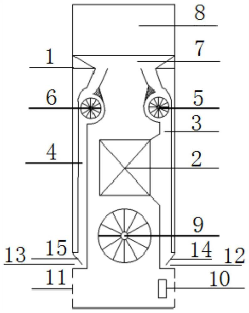
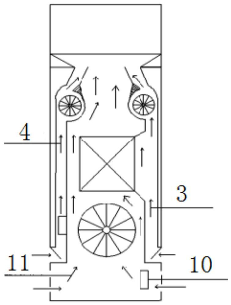
[0024] refer to Figure 1-2 , an air conditioner, comprising a housing 1, a heat exchanger 2 is fixedly installed in the center of the housing 1, and a fresh air duct 3 and a return air duct 3 fixedly installed in the housing 1 are respectively arranged on both sides of the heat exchanger 2. The first impeller 5 and the second impeller 6 are fixedly installed on the top openings of the fresh air duct 3 and the return air duct 4 respectively. The top of the housing 1 is provided with an air outlet 8, and the air outlet 8 is connected to The fresh air duct 3 and the return air duct 4 are connected, the main impeller 9 fixedly installed in the casing 1 is arranged under...


PUM


Abstract

The invention discloses an air conditioning device. The air conditioning device comprises a shell, a heat exchanger is fixedly installed in the center of the interior of the shell, a fresh air duct and a return air duct which are fixedly installed in the shell are arranged on the two sides of the heat exchanger respectively, a first impeller and a second impeller are fixedly installed at the top opening positions of the fresh air duct and the return air duct respectively, and an air outlet is formed in the top of the shell and communicates with the fresh air duct and the return air duct. According to the air conditioner, the air outlet temperature is increased without changing the output capacity of the air conditioner during refrigeration, and the situation that the user experience is affected due to the fact that air with low air outlet temperature is blown out is avoided; meanwhile, the air outlet temperature of refrigeration is increased, the problem that condensation water is likely to be generated on the edge of an air outlet during refrigeration is greatly solved; and besides, a fresh air opening can be opened to replace indoor air, fresh air exchanges heat with the heat exchanger after being introduced and then is blown out, so that the indoor air quality is guaranteed, and meanwhile, the problem of indoor temperature fluctuation caused after the introduction of the fresh air is solved.

Description

technical field [0001] The invention relates to the technical field of air conditioning, in particular to an air conditioning device and a control method. Background technique [0002] At present, the air supply mode of air conditioners in the market is that the indoor air enters the evaporator to exchange heat and blows it out directly. The temperature can easily lead to the formation of condensation water on the air outlet frame, which will affect the user's use; [0003] The fresh air device of the common fresh air conditioner in the market is an independent device, and the fresh air is directly introduced into the room after being filtered, which will easily lead to the phenomenon that the indoor temperature rises during cooling and the indoor temperature decreases during heating, and the introduction of fresh air will change the indoor temperature. This leads to an increase in the power consumption of the air conditioner. Contents of the invention [0004] Based on ...

Claims


Application Information

Patent Timeline
IPC IPC(8): F24F1/0033F24F13/02F24F11/89F24F13/14F24F13/20F24F13/22F24F11/64F24F11/65F24F11/61F24F11/70F24F110/10
CPCF24F1/0033F24F13/02F24F13/14F24F13/20F24F13/22F24F2013/221F24F11/61F24F11/64F24F11/65F24F11/70F24F11/89F24F2110/10Y02B30/70
Inventor 梁章平罗永宏赖路璇吴海宏
Owner GREE ELECTRIC APPLIANCES INC
Learn More