Supercharge Your Innovation With Domain-Expert AI Agents!

Clamp spring pressure detection tool

A tooling and card checking technology, applied in measuring devices, using stable tension/pressure to test the strength of materials, instruments, etc., can solve the problems of poor stability and low accuracy, and achieve the effect of high stability

Pending Publication Date: 2021-03-26
ZHEJIANG MAER FAN MOTOR
View PDF0 Cites 0 Cited by
  • Summary
  • Abstract
  • Description
  • Claims
  • Application Information

AI Technical Summary

Problems solved by technology

The stability of this detection method is relatively poor, and the accuracy is not high

Method used


Image

  • Clamp spring pressure detection tool
  • Clamp spring pressure detection tool

Examples


Embodiment Construction

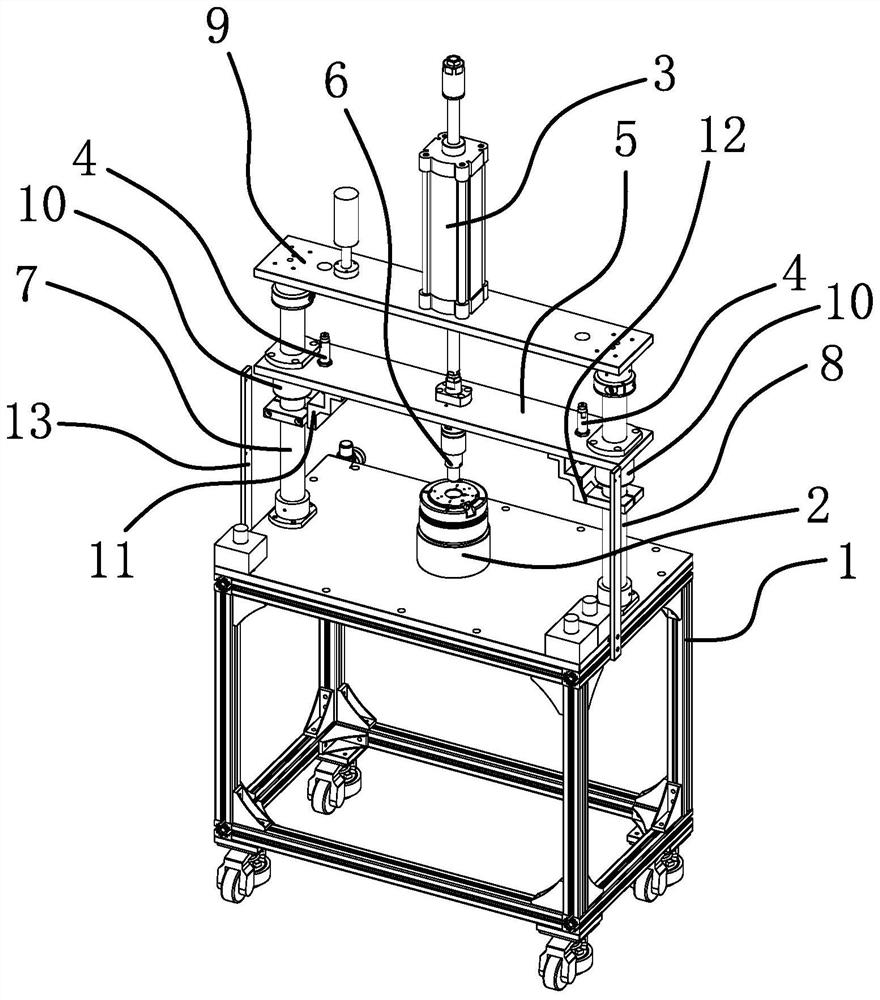
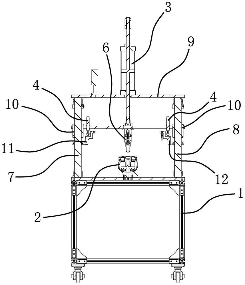
[0030] Such as figure 1 and figure 2 As shown, a pressure detection circlip tooling, including a frame, is characterized in that it also includes a connecting seat, a driver, a sensor, a pressure plate and a contact head. The above connecting seat is used to connect the detected workpiece and the connecting seat is fixed on the machine. At the middle part of the frame, the above-mentioned driving part is fixedly connected to the top of the frame, the above-mentioned pressure plate is connected to the frame and the pressure plate is connected with the driving part, the driving part can drive the pressure plate to move up and down smoothly along the frame, and the above-mentioned contact head is fixedly connected to the lower part of the pressure plate And the contact head is located directly above the connecting seat, the above-mentioned sensor is located between the pressing plate and the frame, and the above-mentioned sensor can detect the displacement of the pressing plate ...


PUM


Abstract

The invention provides a clamp spring pressure detection tool, and belongs to the technical field of machinery. The problem that in the prior art, stability is poor is solved. The clamp spring pressure detection tool comprises a rack and further comprises a connecting base, a driving piece, a sensor, a pressing plate and a contact head, the connecting base is used for being connected with a detected workpiece and fixedly connected to the middle of the rack, the driving piece is fixedly connected to the top of the rack, the pressing plate is connected to the rack, and the pressing plate is connected with the driving piece. The driving piece can drive the pressing plate to stably move up and down along the rack, the contact head is fixedly connected to the lower portion of the pressing plateand located over the connecting base, the sensor is located between the pressing plate and the machine frame, and after the pressing plate moves downwards, the sensor can detect the displacement of the pressing plate. The clamp spring pressure detection tool is high in stability.

Description

technical field [0001] The invention belongs to the technical field of machinery, and relates to a clamp spring tool for pressure detection. Background technique [0002] When extruding the corresponding performance of the test workpiece, the driving part is usually directly used to drive the contact head to move down. [0003] After the contact head moved down presses the workpiece to be tested, it leaves a concave indentation on the workpiece to be tested. By observing the indentation, the corresponding strength parameter performance can be roughly understood. [0004] It can be seen that the existing side view device can only know its corresponding strength parameters through the extruded tested workpiece. The stability of this detection method is relatively poor, and the accuracy is not high. Contents of the invention [0005] The object of the present invention is to solve the above-mentioned problems in the prior art, and provide a high-stability and compact-struc...

Claims


Application Information

Patent Timeline
IPC IPC(8): G01N3/12G01N3/02
CPCG01N3/12G01N3/02G01N2203/0019G01N2203/0044G01N2203/0682
Inventor 王明华李道彬李元星
Owner ZHEJIANG MAER FAN MOTOR
Features
  • R&D
  • Intellectual Property
  • Life Sciences
  • Materials
  • Tech Scout
  • Unparalleled Data Quality
  • Higher Quality Content
  • 60% Fewer Hallucinations
Learn More