Eureka AIR delivers breakthrough ideas for toughest innovation challenges, trusted by R&D personnel around the world.

Indirect evaluation method for frame-core tube structure outer frame rigidity contribution

A core tube and outer frame technology, applied in instrumentation, geometric CAD, design optimization/simulation, etc., can solve the problems of increasing the cross-sectional size of components, misjudging the contribution of outer frame stiffness, and unreasonable design, achieving strong adaptability, Avoid aspect ratios, design well-designed effects

Active Publication Date: 2021-03-26
EAST CHINA ARCHITECTURAL DESIGN & RES INST
View PDF3 Cites 0 Cited by
  • Summary
  • Abstract
  • Description
  • Claims
  • Application Information

AI Technical Summary

Problems solved by technology

However, in the actual design, most super high-rise frame-core tube structures are difficult to meet this requirement. In many projects, the seismic shear force borne by the frame is only 4%-5% of the total structural shear force, which is far from the code requirements, but In order to meet the requirements of the code, the section size of the member must be continuously increased, which not only makes the design unreasonable, but also pays a large economic cost
[0003]In fact, the proportion of shear force sharing cannot always reasonably reflect the ability of the second line of defense of the outer frame, nor is it a very effective index to reflect the contribution of outer frame stiffness. The proportion often misjudgments the contribution of the outer frame stiffness

Method used


Image

  • Indirect evaluation method for frame-core tube structure outer frame rigidity contribution
  • Indirect evaluation method for frame-core tube structure outer frame rigidity contribution
  • Indirect evaluation method for frame-core tube structure outer frame rigidity contribution

Examples


Embodiment Construction

[0023] In order to make the purpose, advantages and features of the present invention clearer, the present invention will be further described in detail below in conjunction with the accompanying drawings and specific embodiments. It should be noted that the drawings are all in very simplified form and not drawn to scale, and are only used to facilitate and clearly assist the purpose of illustrating the embodiments of the present invention. In addition, the structures shown in the drawings are often a part of the actual structure. In particular, each drawing needs to display different emphases, and sometimes uses different scales. It should also be understood that, unless otherwise specified or pointed out, the terms “first”, “second”, “third” and other descriptions in the specification are only used to distinguish each component, element, step, etc. in the specification, rather than It is used to express the logical relationship or sequence relationship between various compo...


PUM


Abstract

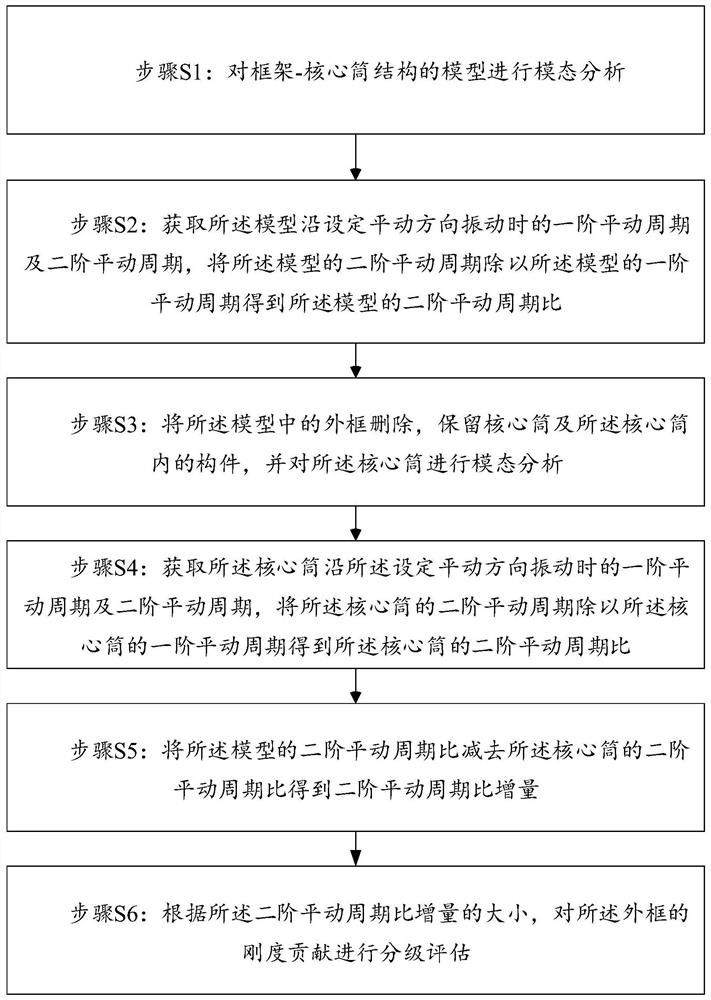
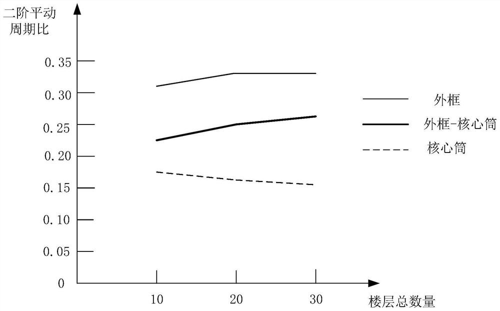
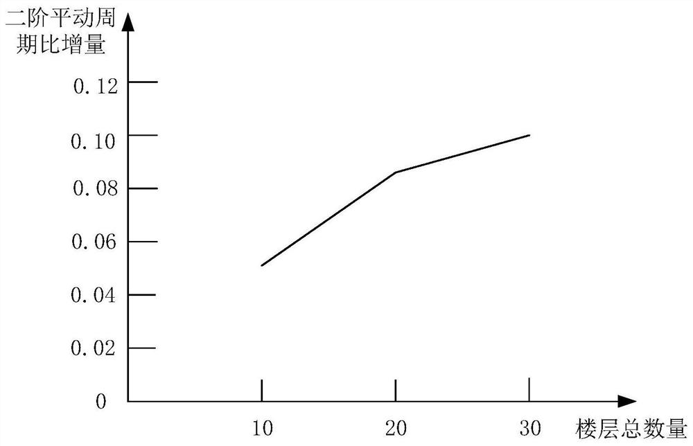
The invention provides an indirect evaluation method for a frame core tube structure outer frame rigidity contribution. The method comprises the following steps: carrying out modal analysis on a modelof the frame core tube structure; obtaining a first-order translation period and a second-order translation period when the model vibrates along a set translation direction, and dividing the second-order translation period of the model by the first-order translation period of the model to obtain a second-order translation period ratio of the model; deleting an outer frame in the model, and carrying out modal analysis on the core tube; obtaining a first-order translation period and a second-order translation period when the core tube vibrates along a set translation direction, and dividing thesecond-order translation period of the core tube by the first-order translation period of the core tube to obtain a second-order translation period ratio; subtracting the second-order translation period ratio of the core tube from the second-order translation period ratio of the model to obtain a second-order translation period ratio increment; and according to the size of the second-order translation period ratio increment, performing grading evaluation on the rigidity contribution of the outer frame. The method is reliable in evaluation result and can provide theoretical support for anti-seismic design of the frame core tube structure.

Description

technical field [0001] The invention relates to the technical field of anti-seismic design of a frame-core tube structure, in particular to an indirect evaluation method for the stiffness contribution of an outer frame of a frame-core tube structure. Background technique [0002] The frame-core tube structure system is the most commonly used double lateral force-resistant structure for high-rise buildings. The system consists of two systems, the frame and the core tube, and they work together to resist external forces. In order to ensure multiple lines of defense under major earthquakes, the seismic codes of many countries have made quantitative regulations on the shear force borne by the frame part. The United States "Internationalbuilding Code 2000" proposes that in a frame-core tube (frame-shear wall) structure, under earthquake action, when the design story shear force of the frame part is not less than 25% of the total shear force of the side force system. my country'...

Claims


Application Information

Patent Timeline
Patent Type & Authority Applications(China)
IPC IPC(8): G06F30/13G06F30/20G06F119/14
CPCG06F30/13G06F30/20G06F2119/14
Inventor 安东亚
Owner EAST CHINA ARCHITECTURAL DESIGN & RES INST
Why Eureka
Eureka Blog
Learn More