A drone charging device

A charging device and drone technology, applied in charging stations, ground devices, electric vehicle charging technology, etc., can solve the problems of high deployment cost, good positioning effect, unstable transmission mode, etc., and achieve stable transmission performance and manufacturing cost. Low, simple and efficient docking method

Active Publication Date: 2021-08-06
涵涡智航科技(玉溪)有限公司
View PDF9 Cites 2 Cited by
  • Summary
  • Abstract
  • Description
  • Claims
  • Application Information

AI Technical Summary

Problems solved by technology

However, the solution of relying on external equipment for energy supply requires precise docking between the drone and the charging base station. The base station and the drone have built-in multiple sensors to assist docking, and the deployment cost is high.
[0003] Patent document CN108482697A discloses a UAV automatic positioning charging device, including a bottom plate for the UAV to land, two parallel first push rods located on both sides of the UAV, and driving the two first push rods for approaching or The first drive mechanism for separation movement, two parallel second push rods located on both sides of the drone, and the second drive mechanism for driving the two second push rods to approach or separate; the first push rod and the second push rod The push rods are distributed vertically; the first push rod is rotated and connected with a limiter that matches the feet of the drone, and a return spring that resets the limiter after rotation; the drone is provided with a horizontal charging interface; the second pusher The pole is provided with a charging connector corresponding to the charging interface; the positioning effect is good, and the docking of the charging connector and the charging interface is completed at the same time as the positioning is completed, and it is also convenient for automatic separation after charging is completed, which provides a good solution for the automatic battery replacement of the drone. Conditions; that is, although the above-mentioned patent documents drive the first push rod and the second push rod respectively through the first drive mechanism and the second drive mechanism to limit the position of the drone so that it is located in the middle of the platform, but its transmission method is simple in structure , Only the limit piece is used to drive the push rod to move, and its transmission mode is unstable

Method used


Image

  • A drone charging device
  • A drone charging device
  • A drone charging device

Examples


Embodiment Construction

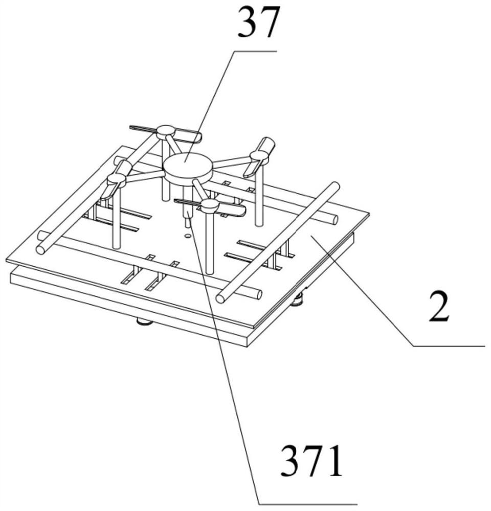
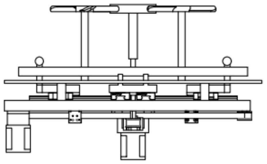
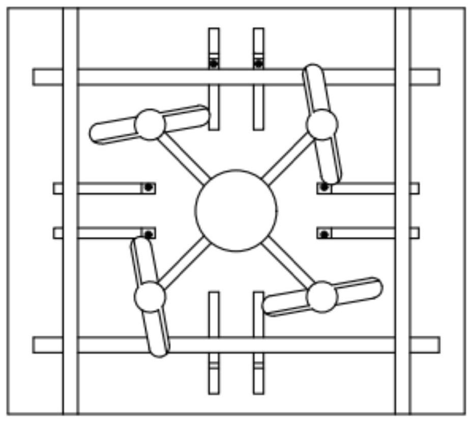
[0041] A drone charging device provided by the present invention will be described in detail below in conjunction with the accompanying drawings.

[0042] refer to Figure 1-10 As shown, a UAV charging device includes a UAV charging positioning mechanism and a charging coil launching platform; the UAV charging positioning mechanism includes a charging platform transmission device, a base plate 1, a UAV landing plate 2 and a positioning device ; The charging platform transmission device includes a front and rear transmission device and a left and right transmission device, and the positioning device includes a left and right positioning device and a front and rear positioning device;

[0043] Wherein, the front and rear transmission device provided by the present invention includes a first motor 3, a front and rear synchronous belt 4, a front synchronous wheel 5, a rear synchronous wheel 6, a front mobile link block 7 and a rear mobile link block 8, and the first motor 3 is con...


PUM


Abstract

The invention provides a UAV charging device, including a UAV charging positioning mechanism and a charging coil launching platform; the UAV charging and positioning mechanism includes a charging platform transmission device, a bottom plate, a UAV landing plate and a positioning device; The charging platform transmission device includes a front and rear transmission device and a left and right transmission device, and the positioning device includes a left and right positioning device and a front and rear positioning device; after the UAV of the present invention locates the base station by GPS, it lands on the UAV landing area. The interactive mode of the human-machine charging and positioning mechanism can accurately dock with the charging coil launch platform. The docking method is simple and efficient. The R&D and manufacturing costs of the base station and the corresponding module of the drone are low, reducing the dependence of the drone on sensors.

Description

technical field [0001] The invention relates to the field of unmanned aerial vehicle charging, in particular to an unmanned aerial vehicle charging device. Background technique [0002] Short battery life is an important reason restricting the development of the multi-rotor drone industry. Multi-rotor drones (hereinafter referred to as drones) need to provide lift to offset their own weight. Generally, the battery life is within 30 minutes. Endurance has become the focus of current industry research. The current battery life solution for UAVs is mainly to charge UAVs through external devices. However, the solution of relying on external equipment for energy supply requires precise docking between the UAV and the charging base station. The base station and the UAV have built-in multiple sensors to assist in the docking, and the deployment cost is high. [0003] Patent document CN108482697A discloses a UAV automatic positioning charging device, including a bottom plate for t...

Claims


Application Information

Patent Timeline
Patent Type & Authority Patents(China)
IPC IPC(8): B60L53/35B60L53/38B64F1/00
CPCB60L53/35B60L53/38B64F1/00B60L2200/10B64U10/10B64U30/20B64U50/19Y02T10/70Y02T10/7072Y02T90/12
Inventor 马玉宁
Owner 涵涡智航科技(玉溪)有限公司
Why Eureka
Try Eureka