
Outdoor pan-tilt windproof mechanism

A cloud platform, No. 1 technology, applied in the field of cloud platform, can solve the problems of reducing the bearing area and bearing range of the main body of the platform, reducing the load-bearing performance of the main body of the platform, and failing to achieve the wind resistance performance of the outdoor platform, so as to increase the bearing capacity of the platform. Effect of wind performance, increased flexibility and stability, improved rigidity

Pending Publication Date: 2021-03-30
ANHUI XUCHENDA ELECTRONICS TECH
View PDF0 Cites 0 Cited by
  • Summary
  • Abstract
  • Description
  • Claims
  • Application Information

AI Technical Summary

Problems solved by technology

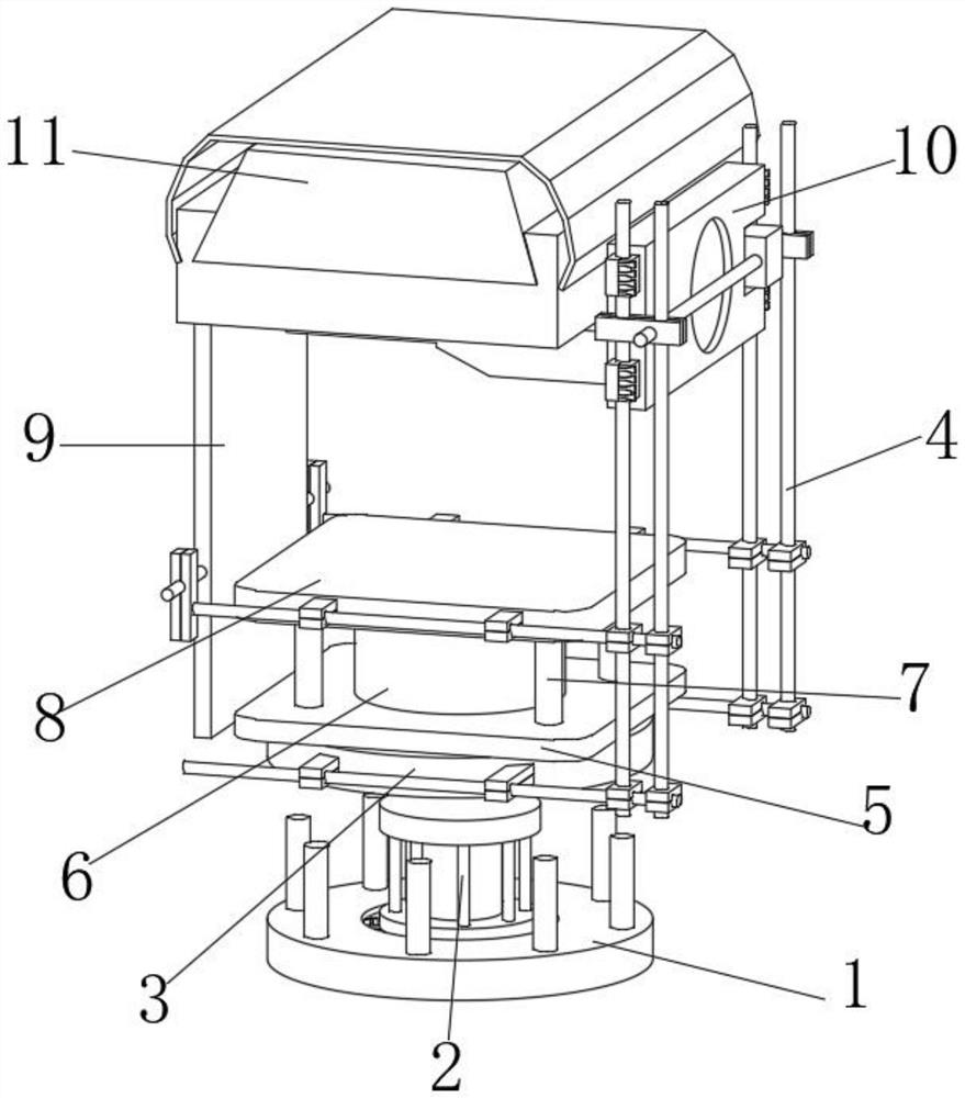
The electric pan / tilt is suitable for scanning and monitoring a large area. It can expand the surveillance range of the camera. 1. In the existing pan / tilt windproof device, the stability of the main body rotation of the pan / tilt is reduced, and the rigidity of the bottom plate rotation is reduced. There is a phenomenon that the main body of the pan-tilt shakes left and right or tilts when it rotates; 2. In the existing anti-wind device of the pan-tilt, the wind-resistant performance of the main body of the pan-tilt is reduced, and the possibility of swinging the main body of the pan-tilt under the influence of wind force in an outdoor environment is increased. Achieve the effect of improving the wind resistance performance of the outdoor cloud platform; 3. In the existing cloud platform windproof device, it is easy to appear the phenomenon of deviation caused by the wind force during the bearing process, which reduces the bearing area and bearing range of the main body of the cloud platform, and reduces the impact of the cloud platform. The load-bearing performance of the main body; therefore, we propose an outdoor pan-tilt windproof mechanism

Method used


Image

  • Outdoor pan-tilt windproof mechanism
  • Outdoor pan-tilt windproof mechanism
  • Outdoor pan-tilt windproof mechanism

Examples


Embodiment Construction

[0027] In order to make the technical means, creative features, goals and effects achieved by the present invention easy to understand, the present invention will be further described below in conjunction with specific embodiments.

[0028] In the description of the present invention, it should be noted that the terms "upper", "lower", "inner", "outer", "front end", "rear end", "both ends", "one end", "another end" The orientation or positional relationship indicated by etc. is based on the orientation or positional relationship shown in the drawings, and is only for the convenience of describing the present invention and simplifying the description, rather than indicating or implying that the referred device or element must have a specific orientation, use a specific Azimuth configuration and operation, therefore, should not be construed as limiting the invention. In addition, the terms "first" and "second" are used for descriptive purposes only, and should not be understood ...


PUM


Abstract

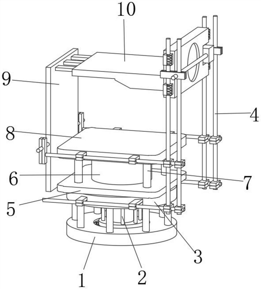
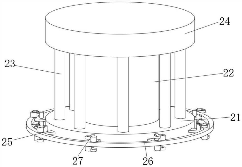
The invention discloses an outdoor pan-tilt windproof mechanism. The outdoor pan-tilt windproof mechanism comprises a bottom plate, wherein the middle of the upper end of the bottom plate is movably connected with a rotating structure; the upper end of the rotating structure is fixedly connected with a connecting frame; the front end and the rear end of the connecting frame are jointly and fixedlyconnected with a stabilizing structure; the upper ends of a fixing column and four supporting columns are jointly and fixedly connected with an upper connecting plate; the left end of a lower connecting plate and the left end of the upper connecting plate are jointly and fixedly connected with a supporting frame; and the left portion of the upper end of the stabilizing structure is fixedly connected with a bearing structure. According to the outdoor pan-tilt windproof mechanism, by arranging the rotating structure, the stabilizing structure and the bearing structure, the rotating rigidity ofthe bottom plate is improved, the phenomenon that a pan-tilt main body shakes left and right or inclines when rotating is avoided, the possibility that the pan-tilt main body swings under the influence of wind power in the outdoor environment can be reduced advantageously, the effect of improving the wind resistance of an outdoor pan-tilt is achieved, the bearing area and the bearing range of thepan-tilt main body are enlarged, and the load bearing performance of the pan-tilt main body is improved.

Description

technical field [0001] The invention relates to the field of cloud platform technology, in particular to an outdoor cloud platform windproof mechanism. Background technique [0002] The pan / tilt is a supporting device for installing and fixing the camera, and it is divided into two types: fixed and electric pan / tilt. The fixed pan / tilt is suitable for the situation where the monitoring range is not large. After installing the camera on the fixed pan / tilt, you can adjust the horizontal and pitch angles of the camera. After reaching the best working posture, you only need to lock the adjustment mechanism. The electric pan / tilt is suitable for scanning and monitoring a large area. It can expand the surveillance range of the camera. 1. In the existing pan / tilt windproof device, the stability of the main body rotation of the pan / tilt is reduced, and the rigidity of the bottom plate rotation is reduced. There is a phenomenon that the main body of the pan-tilt shakes left and righ...

Claims


Application Information

Patent Timeline
IPC IPC(8): F16M11/22F16M11/02F16M11/08F16M11/20
CPCF16M11/02F16M11/08F16M11/2014F16M11/22
Inventor 刘晨
Owner ANHUI XUCHENDA ELECTRONICS TECH
Learn More