Optical system, lens module and electronic equipment

An optical system and lens technology, applied in optics, optical components, instruments, etc., can solve the problems of not being able to follow the general trend of technological development, difficulty in miniaturization, and difficulty in reducing the size of the lens

Pending Publication Date: 2021-03-30
JIANGXI JINGCHAO OPTICAL CO LTD
View PDF0 Cites 2 Cited by
  • Summary
  • Abstract
  • Description
  • Claims
  • Application Information

AI Technical Summary

Problems solved by technology

The size of the existing lens is not easy to reduce, it is difficult to miniaturize, and the imaging quality of the distant details is not good, it cannot conform to the general trend of technological development, and it is difficult to apply to the mainstream mobile phone market

Method used


Image

  • Optical system, lens module and electronic equipment
  • Optical system, lens module and electronic equipment
  • Optical system, lens module and electronic equipment

Examples


no. 1 example

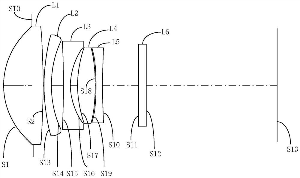
[0057] Please refer to Figure 1A with Figure 1B , The optical system of the present embodiment includes side to image side in the optical axis direction, including:

[0058] The first lens L1, having a positive optical focus, the object side surface S1 of the first lens L1 is a convex surface, and the image side surface S2 of the first lens L1 is a convex surface.

[0059] The second lens L2, having a positive optical focus, the side surface S3 of the second lens L2 is a convex surface, and the image side surface S4 of the second lens L2 is a concave surface.

[0060] The third lens L3, having a negative optical focus, the side surface S5 of the third lens L3 is a concave surface, and the image side surface S6 of the third lens L3 is a concave surface.

[0061] The fourth lens L4, having a positive optical focus, the side surface S7 of the fourth lens L4 is a convex surface, and the image side surface S8 of the fourth lens L4 is a convex surface.

[0062] The fifth lens L5, havi...

no. 2 example

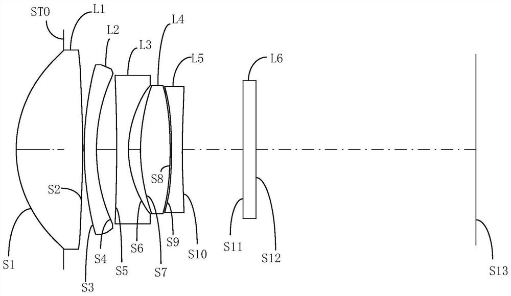
[0079] Please refer to Figure 2A with Figure 2b , The optical system of the present embodiment includes side to image side in the optical axis direction, including:

[0080] The first lens L1, having a positive optical focus, the object side surface S1 of the first lens L1 is a convex surface, and the image side surface S2 of the first lens L1 is a convex surface.

[0081] The second lens L2, having a negative light, the side surface S3 of the second lens L2 is a convex surface, and the image side surface S4 of the second lens L2 is a concave surface.

[0082] The third lens L3, having a negative optical focus, the side surface S5 of the third lens L3 is a concave surface, and the image side surface S6 of the third lens L3 is a concave surface.

[0083] The fourth lens L4, having a positive optical focus, the side surface S7 of the fourth lens L4 is a convex surface, and the image side surface S8 of the fourth lens L4 is a convex surface.

[0084] The fifth lens L5, having a neg...

no. 3 example

[0096] Please refer to Figure 3A with Figure 3B , The optical system of the present embodiment includes side to image side in the optical axis direction, including:

[0097] The first lens L1, having a positive optical focus, the object side surface S1 of the first lens L1 is a convex surface, and the image side surface S2 of the first lens L1 is a convex surface.

[0098] The second lens L2, having a negative light, the side surface S3 of the second lens L2 is a convex surface, and the image side surface S4 of the second lens L2 is a concave surface.

[0099] The third lens L3, having a negative optical focus, the side surface S5 of the third lens L3 is a concave surface, and the image side surface S6 of the third lens L3 is a concave surface.

[0100] The fourth lens L4, having a positive optical focus, the side surface S7 of the fourth lens L4 is a convex surface, and the image side surface S8 of the fourth lens L4 is a convex surface.

[0101] The fifth lens L5, having a neg...


PUM


Abstract

The invention provides an optical system, a lens module and electronic equipment. The optical system sequentially comprises a first lens, a second lens, a third lens, a fourth lens, a fifth lens fromthe object side to the image side in the optical axis direction. The first lens has positive power, the second lens has focal power; The third lens has negative focal power; the fourth lens has positive focal power, and the object side surface and the image side surface of the fourth lens are convex surfaces; the fifth lens has negative focal power; wherein the optical system meets the following relational expressions: 0.2<TD/f<0.5; wherein TD is the distance from the object side surface of the first lens to the image side surface of the fifth lens on the optical axis, f is the effective focallength of the optical system, and by reasonably configuring the surface types and focal power of the lenses from the first lens to the fifth lens, the long-focal-length telescopic function is achieved, and the requirements for miniaturization and high imaging quality are met.

Description

Technical field [0001] The present invention relates to the field of optical imaging, and more particularly to an optical system, a lens module, and an electronic device. Background technique [0002] In recent years, with the continuous development of smartphone related technology, mobile phone lens miniaturization and high quality imaging quality are increasing, and as the semiconductor technology is refined, the pixel size of the photosensitive element is reduced, and the light and short appearance Excellent electronic products must become a development trend. The imaging module is increasingly widely used, and the camera module is used in various intelligent electronics, in-vehicle devices, identification systems, entertainment sports equipment will also become a major trend in the future. [0003] Like today, the mobile phone is equipped with two or more different image functions, has become the mainstream of the mobile phone market. The size of the existing lens is not easi...

Claims


Application Information

Patent Timeline
Patent Type & Authority Applications(China)
IPC IPC(8): G02B13/00G02B13/02G02B13/16G02B13/18
CPCG02B13/0045G02B13/02G02B13/16G02B13/18
Inventor 邹金华李明刘彬彬
Owner JIANGXI JINGCHAO OPTICAL CO LTD
Why Eureka
Try Eureka