A fast packaging system and method for fresh food transportation
A packaging system and fresh food technology, which is applied in the direction of transportation packaging, transportation and packaging, packaging, etc., can solve the problems that fresh packaging boxes cannot be automatically wrapped and packaged, and the wrapping tape cannot be automatically cut off, so as to achieve convenient operation and use, good effect, The effect of large winding area
- Summary
- Abstract
- Description
- Claims
- Application Information
AI Technical Summary
Problems solved by technology
Method used
Image
Examples
specific Embodiment approach 1
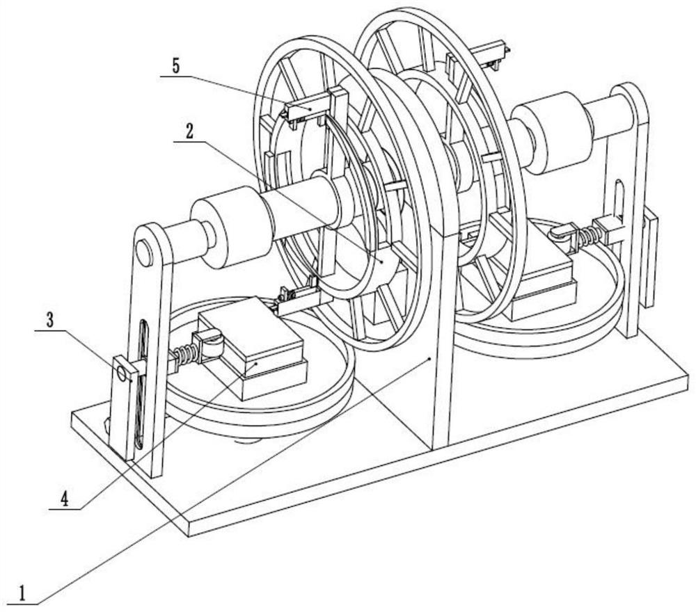
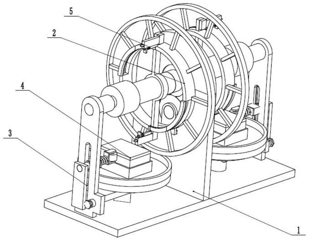
[0031] like Figure 1 to Figure 10As shown, a rapid packaging system for fresh transport includes a rack base 1, a winding and cutting drive 2, two winding synchronizing compressors 3, two rotating lifting platforms 4 and four reverse spring cutting edges 5. The winding cutting driver 2 is fixedly connected to the middle end of the rack base 1, the two ends of the winding cutting driver 2 are rotatably connected in the rack base 1, and the two winding synchronous compressors 3 are respectively longitudinally slidably connected to the rack. At both ends of the base 1, the two winding synchronous compressors 3 are respectively connected to the two rotating lifting platforms 4 through the meshing transmission of the helical gears. The spring cutting edge 5 is evenly and firmly connected to the winding cutting drive 2 . The fresh packaging box to be packaged is placed on the two rotating lifting platforms 4, and the winding and cutting driver 2 is pressed and attached to the fres...
specific Embodiment approach 2
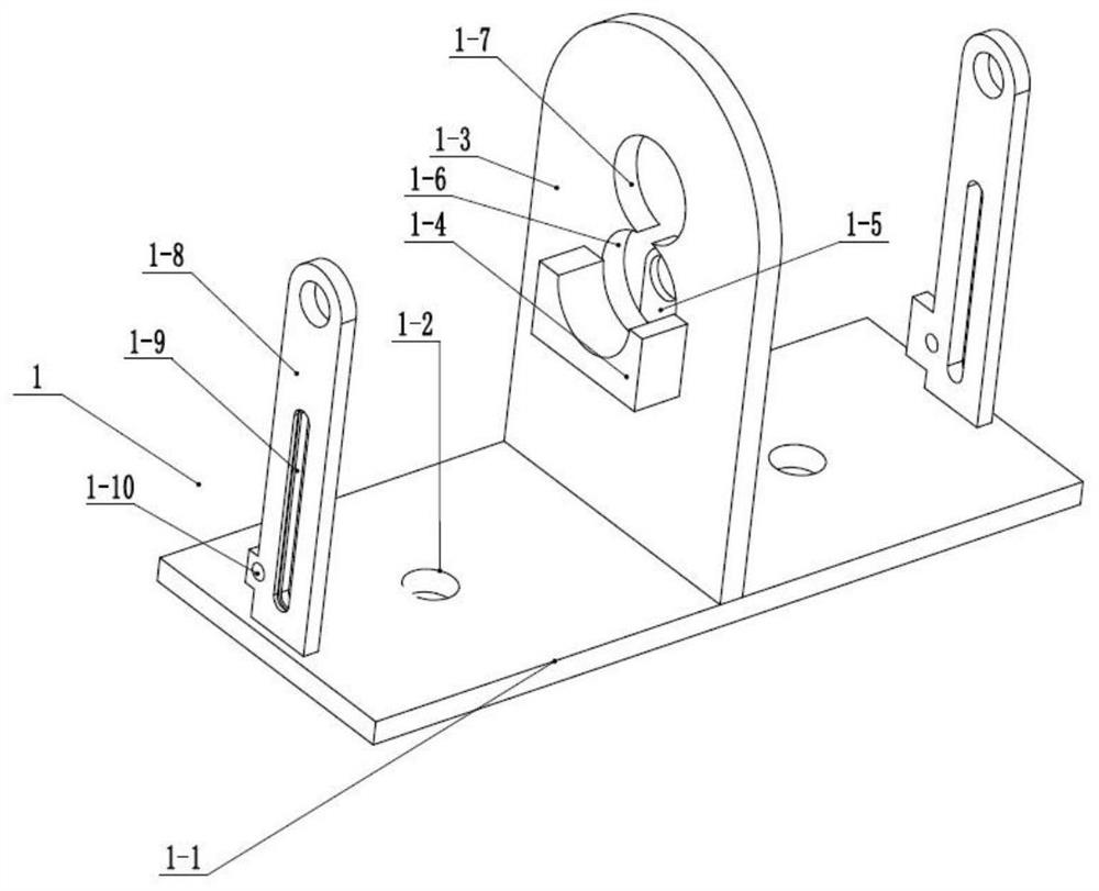
[0032] like Figure 1 to Figure 10 As shown, this embodiment further describes the first embodiment, the frame base 1 includes a bottom plate 1-1, two rotating circular holes 1-2, a central fixing plate 1-3, a motor fixing seat 1-4, a shaft Rotation table 1-5, lower rotation round hole 1-6, upper rotation round hole 1-7, two side fixed slide tables 1-8, two inner chute 1-9 and two side rotation round holes 1-10 , the bottom plate 1-1 is evenly provided with two rotating round holes 1-2, the central fixing plate 1-3 is fixedly connected to the middle end of the bottom plate 1-1, the motor fixing seat 1-4 and the shaft turning table 1-5 are respectively fixed Connected to both ends of the central fixing plate 1-3, the lower rotating circular hole 1-6 and the upper rotating circular hole 1-7 are both arranged on the central fixing plate 1-3, and the lower rotating circular hole 1-6 is connected to the upper rotating circular hole 1-7, the two side fixed sliding tables 1-8 are fi...
specific Embodiment approach 3
[0033] like Figure 1 to Figure 10 As shown, this embodiment further describes the second embodiment. The winding and cutting driver 2 includes a driving motor 2-1, a driving gear 2-2, a central gear 2-3, a central rotating shaft 2-4 and two tape releasers. Roller 2-5, drive motor 2-1 is fixedly connected to the motor holder 1-4, the drive shaft of the drive motor 2-1 is rotatably connected to the shaft turntable 1-5, and the drive gear 2-2 is fixedly connected to the drive On the transmission shaft of the motor 2-1, the driving gear 2-2 meshes with the central gear 2-3, and the driving gear 2-2 and the central gear 2-3 are rotatably connected to the lower rotating circular hole 1-6 and the upper rotating circular hole 1 respectively. In -7, the central gear 2-3 is fixedly connected to the central rotating shaft 2-4, the two ends of the central rotating shaft 2-4 are respectively connected to the two side fixed sliding tables 1-8, and the two tape unwinding rollers 2- 5 are s...
PUM
 Abstract
Description
Claims
Application Information
 - R&D
- Intellectual Property
- Life Sciences
- Materials
- Tech Scout
- Unparalleled Data Quality
- Higher Quality Content
- 60% Fewer Hallucinations
Browse by: Latest US Patents, China's latest patents, Technical Efficacy Thesaurus, Application Domain, Technology Topic, Popular Technical Reports.
© 2025 PatSnap. All rights reserved.Legal|Privacy policy|Modern Slavery Act Transparency Statement|Sitemap|About US| Contact US: help@patsnap.com


