Big arm mechanism

A boom and arm shaft technology, applied in the field of boom mechanisms, can solve the problems of unfavorable overall robot balance, inability to guarantee reliable operation, time-consuming and labor-intensive problems, and achieve the effect of no hydraulic oil leakage, good use effect and broad market prospect

Pending Publication Date: 2021-04-02
POWERCHINA XIBEI ENG +1
View PDF0 Cites 0 Cited by
  • Summary
  • Abstract
  • Description
  • Claims
  • Application Information

AI Technical Summary

Problems solved by technology

[0004] The purpose of the present invention is to provide a boom mechanism to solve the problem in the background art that a single oil cylinder is not conduciv

Method used


Image

  • Big arm mechanism
  • Big arm mechanism
  • Big arm mechanism

Examples


Embodiment Construction

[0026] The following will clearly and completely describe the technical solutions in the embodiments of the present invention with reference to the accompanying drawings in the embodiments of the present invention. Obviously, the described embodiments are only some, not all, embodiments of the present invention. Based on the embodiments of the present invention, all other embodiments obtained by persons of ordinary skill in the art without making creative efforts belong to the protection scope of the present invention.

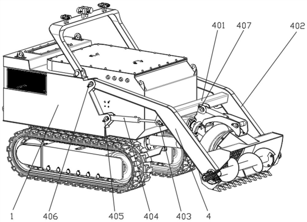
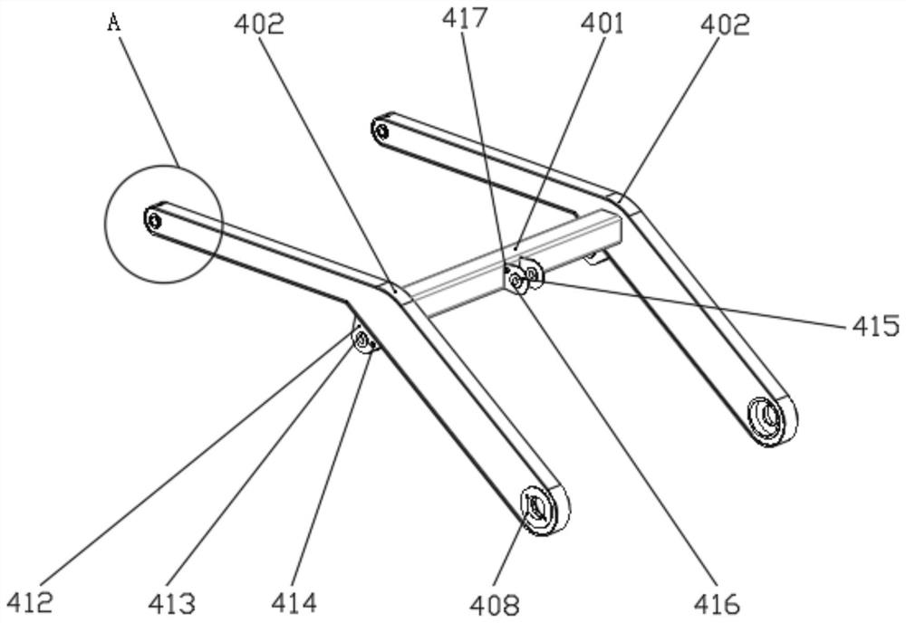
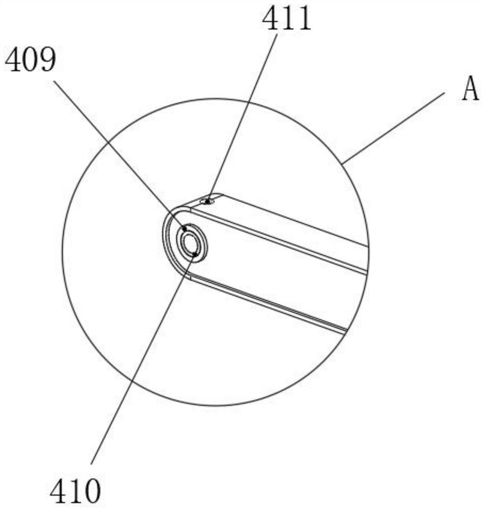
[0027] see Figure 1-6 , the present invention provides a technical solution: figure 1 and figure 2 Among them, the boom mechanism is installed on the body 1 of the dredging robot to support and adjust the angle and height of its raking screw mechanism, so that the coaxial linkage mechanism of the big arm assembly drives the raking screw in different positions. position work, the boom mechanism 4 includes a connecting square tube 401 and a big arm 402 arran...


PUM


Abstract

The invention discloses a big arm mechanism. The big arm mechanism is installed on a vehicle body of a desilting robot and comprises a connecting square pipe and big arms arranged on the two sides ofthe connecting square pipe, wherein the two ends of the connecting square pipe are welded to the two big arms, the positions, close to the square pipe, of the bottom faces of the big arms are rotationally connected with piston ends of big arm lifting oil cylinders through lifting oil cylinder piston pin shafts, cylinder body ends of the big arm lifting oil cylinders are located on the lower sidesof the big arms and rotationally connected to the vehicle body through lifting oil cylinder body pin shafts, and the large-arm lifting oil cylinders are used for driving the large arms to move up anddown on the vehicle body. According to the big arm mechanism, aiming at the defects of the existing equipment, the large arms and the large arm lifting oil cylinders are designed to be symmetrically arranged, so that the balance moment is favorably obtained, and the operation is more reliable; and the height of a trailing suction screw is adjusted, the working efficiency is greatly improved underthe condition that the dredging effect is guaranteed, the risk of hydraulic oil leakage is avoided, the using effect is good, and the market prospect is wide.

Description

technical field [0001] The invention relates to the technical field of mechanical transmission, and the specific field is a boom mechanism. Background technique [0002] With the rapid development of urbanization in our country, the construction scale of urban drainage system is also expanding further. And existing urban drainage mainly relies on underground pipeline, box culvert to dredge. This kind of drainage method will inevitably lead to silt deposition in the long-term accumulation, and various situations such as pipeline and box culvert blockage and sewage overflow will gradually appear. Especially in the flood season, the urban drainage is blocked, and the road surface caused by the silt deposit is seriously waterlogged, which even leads to the interruption of the traffic on the road section, which seriously affects the life and production of the citizens, pollutes the environment, and causes huge losses to the social economy. The speed of a city's development main...

Claims


Application Information

Patent Timeline
IPC IPC(8): E03F7/10E03F9/00
CPCE03F7/10E03F7/106E03F9/002
Inventor 周恒石立宋政昌张伟肖斌王丹迪郝鑫
Owner POWERCHINA XIBEI ENG
Why Eureka
Try Eureka