Large-span and small-deflection T-shaped blade applied to blind window and curtain wall
A large-span, louvered blade technology, applied in the field of shutters, can solve the problems of large deflection of blades, achieve the effects of reducing deflection, small stacking height, and avoiding deformation or damage
- Summary
- Abstract
- Description
- Claims
- Application Information
AI Technical Summary
Problems solved by technology
Method used
Image
Examples
Embodiment 1
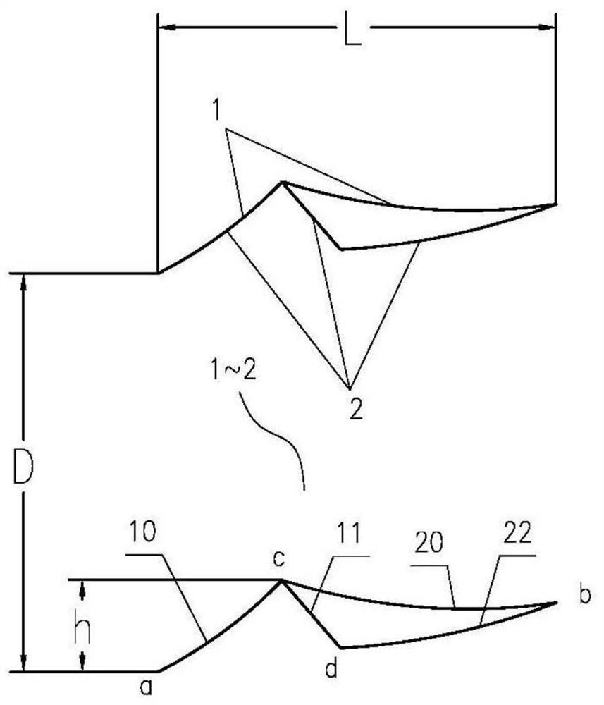
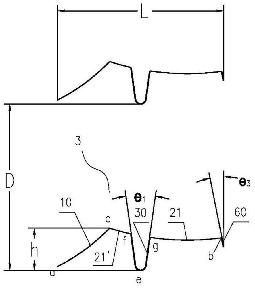
[0081] Please also refer to Figure 1 ~ Figure 2 , this embodiment 1 provides a figure 1 The small deflection blade 3 evolved from the blade 1 of the shutter I shown is applied to the shutter II, including the front part 21' of the reflector, the groove 30 and the light guide plate, wherein the reflector 10 is arc-shaped, and is used to illuminate the The incident light on the reflector 10 is reflected back to the outside, and the light guide plate is arc-shaped, interrupted by the groove 30 to form two parts, the front part 21' of the light guide plate and the rear part 21 of the light guide plate, as figure 2 As shown, it is used to deflect the incident light irradiated on the light guide plate and introduce it to the indoor ceiling. The groove 30 is arranged in the middle of the cross section of the blade 3, and the groove 30 is along the front part 21' of the light guide plate and the rear part 21 of the light guide plate. In order to reduce the deflection of the blade 3...
Embodiment 2
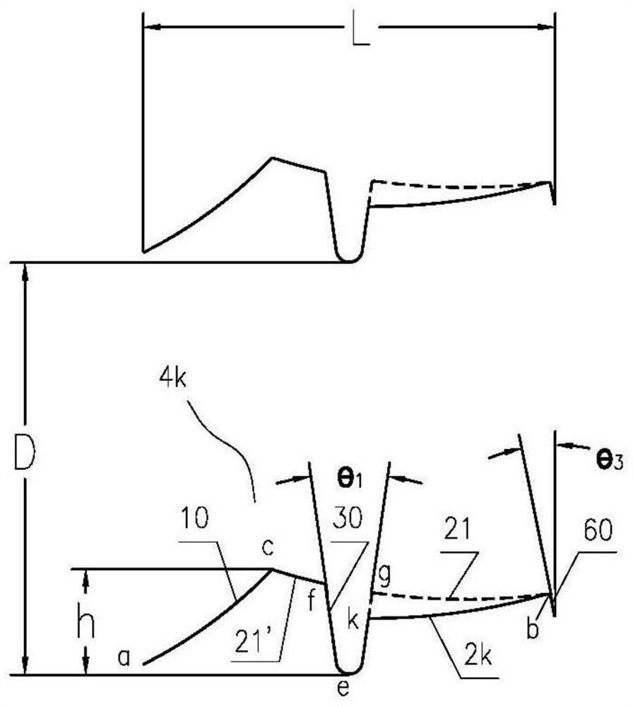
[0085] see image 3 , this embodiment 2 provides a figure 2 The T-shaped blade 4k evolved from the blade 3 of the louver II shown is applied to the louver II. The dotted line 21 in the figure is the rear part 21 of the light guide plate of the blade 3, including the reflector 10, the transition plate 21', and the groove 30 And the light guide plate 2k, wherein, the reflector 10, the transition plate 21' and the groove 30 respectively refer to the corresponding parts of the blade 3, the light guide plate 2k is arc-shaped, and is used to deflect the incident light irradiated on it and guide it to the indoor ceiling or upper On the backlight surface of a blade, the light guide plate 2k is obtained by rotating the light guide plate 21 of the blade 3 downward around its inner side b and the extension of one end thereof intersects at 1 / 3 from the top g on the right side of the groove 30 to the bottom e of the groove at k The inner bending edge 60 of the light guide plate 2k refers...
Embodiment 3
[0088] see Figure 4 , this embodiment 3 provides a figure 2 The T-shaped blade 4q evolved from the blade 3 of the shutter II shown is applied to the shutter II. The dotted line 21 in the figure is the rear part 21 of the light guide plate of the blade 3, including the reflector 10, the transition plate 21', and the groove 30 And the light guide plate 2q, wherein, the reflector 10, the transition plate 21' and the groove 30 respectively refer to the corresponding parts of the blade 3, the light guide plate 2q is arc-shaped, and is used to deflect the incident light irradiated on it and guide it to the indoor ceiling or upper On the backlight surface of a blade, the light guide plate 2q is obtained by rotating the light guide plate 21 of the blade 3 downward around its inner side b and the extension of one end intersects with 2 / 3 of the groove 30 from the top g on the right side to the bottom e of the groove and q The inner bending edge 60 of the light guide plate 2q refers t...
PUM
 Abstract
Description
Claims
Application Information
 - R&D
- Intellectual Property
- Life Sciences
- Materials
- Tech Scout
- Unparalleled Data Quality
- Higher Quality Content
- 60% Fewer Hallucinations
Browse by: Latest US Patents, China's latest patents, Technical Efficacy Thesaurus, Application Domain, Technology Topic, Popular Technical Reports.
© 2025 PatSnap. All rights reserved.Legal|Privacy policy|Modern Slavery Act Transparency Statement|Sitemap|About US| Contact US: help@patsnap.com


