Lamp diffuser plate thickness detection device

A thickness detection and diffusion plate technology, applied in sorting and other directions, can solve problems such as the inability to separate diffusion plates of different thicknesses, and the inability to detect the thickness of diffusion plates.

Inactive Publication Date: 2021-04-06
九江市哥瑞照明电器有限公司
View PDF9 Cites 3 Cited by
  • Summary
  • Abstract
  • Description
  • Claims
  • Application Information

AI Technical Summary

Problems solved by technology

[0005] In order to overcome the shortcomings that the current method of detecting the diffusion plate cannot detect the thickness of the diffusion plate and cannot separate the diffusion plates with different thicknesses, the purpose of the present invention is to provide a method that can automatically detect the thickness of the diffusion plate and separate the thickness of the diffusion plate. Diffusion plate thickness detection device for different diffuser plates

Method used


Image

  • Lamp diffuser plate thickness detection device
  • Lamp diffuser plate thickness detection device
  • Lamp diffuser plate thickness detection device

Examples


Embodiment 1

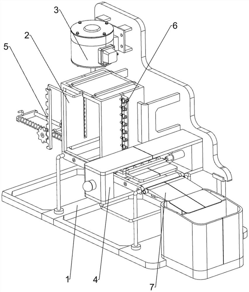
[0023] A device for detecting the thickness of a diffuser plate of a lamp, such as Figure 1-Figure 5 As shown, it includes a mounting base 1, a blanking assembly 2, a pushing assembly 3 and a detection assembly 4. The mounting base 1 is used to install the entire device, and the left part of the mounting base 1 is provided with a blanking assembly 2 that performs blanking by sliding The upper part of the right side of the mounting base 1 is provided with a pusher assembly 3 that provides power for material pushing, and the right part of the mounting base 1 is provided with a detection assembly 4 through laser detection.

[0024] When it is necessary to detect the thickness of the diffusion plate, the staff first places a certain amount of diffusion plate into the blanking assembly 2, and then starts the pushing assembly 3 to push the diffusion plate in the blanking assembly 2 to the bottom of the detection assembly 4, and then The staff can collect the diffuser plates that ha...

Embodiment 2

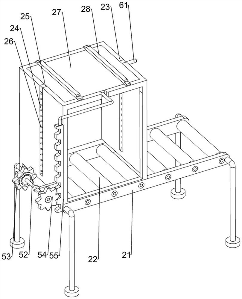
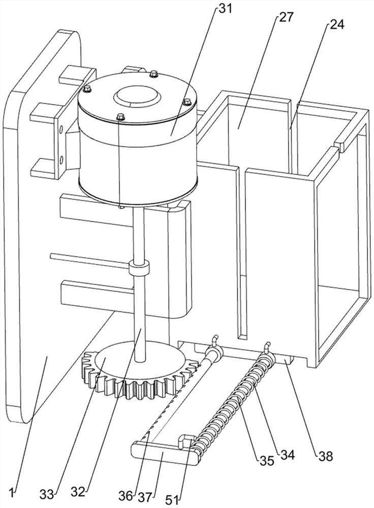
[0032] On the basis of Example 1, such as figure 1 with figure 2 As shown, the push assembly 5 includes an L-shaped rod 51, an overrunning clutch 52, a first gear 53, a second gear 54 and a rack 55, the front side of the connecting plate 37 is welded with an L-shaped rod 51, and the lower part of the left side of the frame body 23 The rotary type is provided with an overrunning clutch 52, the outside of the overrunning clutch 52 is provided with a first gear 53, the first gear 53 cooperates with the L-shaped bar 51, the front end of the overrunning clutch 52 transmission shaft is provided with a second gear 54, and the front side of the pressing plate 27 is fixed by screws. A rack 55 is connected, and the rack 55 cooperates with the second gear 54 .

[0033] When the connecting plate 37 moves to the right, it drives the L-shaped bar 51 to move to the right. When the L-shaped bar 51 contacts the first gear 53, it pushes the first gear 53 to rotate, and drives the overrunning ...


PUM


Abstract

The invention relates to a detection device, in particular to a lamp diffuser plate thickness detection device. The lamp diffuser plate thickness detection device can automatically detect the thicknesses of diffuser plates and separate the diffuser plates with different thicknesses. The lamp diffuser plate thickness detection device comprises a mounting base, a discharging assembly, a pushing assembly and a detection assembly, wherein the mounting base is used for mounting the whole device; the discharging assembly is mounted on the mounting base and conducts discharging in a sliding mode; the pushing assembly is mounted on the mounting base and provides power for pushing; and the detection assembly is mounted on the mounting base and conducts laser detection. Through cooperation of a frame body and a pressing plate, the diffuser plates can be stably moved downwards and can be rapidly guided to move; through cooperation of a sector gear and a toothed bar, the diffuser plates can be rapidly pushed to a specified position; and through cooperation of an infrared emitter and an infrared receiver, the thicknesses of the diffuser plates can be rapidly and accurately detected, and workers can conveniently conduct separate collection.

Description

technical field [0001] The invention relates to a detection device, in particular to a detection device for the thickness of a diffuser plate of a lamp. Background technique [0002] The biggest feature of the diffusion plate is that it causes great interference to the light. No matter how much the original design light distribution curve is, the surface of the lamp will feel like a layer of fog. Carry out strict control testing. [0003] Patent Publication No. CN108706151A discloses a diffusion plate detection and packaging line, including a detection box, a placement plate, a film passing device and a heat shrinking device. The bottom of the detection box is fixedly connected with a first base, and the inside of the detection box is fixedly connected with a The first telescopic rod, the top of the first telescopic rod is fixedly connected with an arc-shaped shell, and the top of the inner surface of the arc-shaped shell is fixedly connected with a fixed block, and the lef...

Claims


Application Information

Patent Timeline
Patent Type & Authority Applications(China)
IPC IPC(8): B07C5/36B07C5/10
CPCB07C5/362B07C5/10
Inventor 袁嘉妮
Owner 九江市哥瑞照明电器有限公司
Why Eureka
Try Eureka