Optical imaging lens

An optical imaging lens, lens technology, used in optics, optical components, instruments, etc., to achieve the effect of high pixel volume

Active Publication Date: 2021-04-06
JIANGXI LIANYI OPTICS CO LTD
View PDF3 Cites 3 Cited by
  • Summary
  • Abstract
  • Description
  • Claims
  • Application Information

AI Technical Summary

Problems solved by technology

However, when pursuing high-quality photos, it is often affected by the thinner and lighter requirements of mobile phones and the limitation of the total length of the lens.

Method used


Image

  • Optical imaging lens
  • Optical imaging lens
  • Optical imaging lens

Examples


Embodiment 1

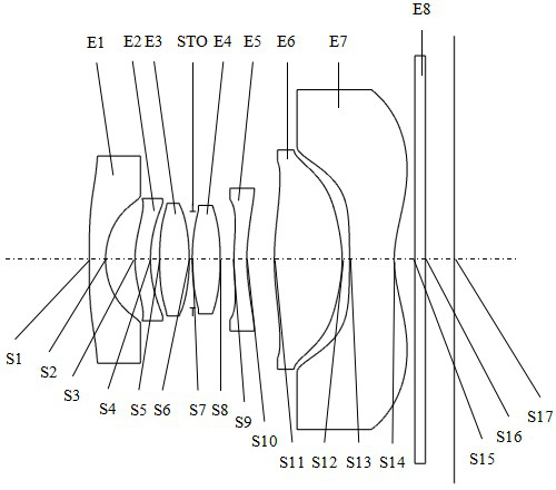
[0084] figure 1 A schematic structural diagram of an optical imaging lens according to Embodiment 1 of the present application is shown. The optical imaging lens includes in sequence from the object side to the image side: the first lens E1, the second lens E2, the diaphragm STO, the third lens E3, the fourth lens E4, the fifth lens E5, the sixth lens E6, and the seventh lens E7, filter E8 and imaging surface S17.

[0085] The first lens E1 has negative refractive power, its object side S1 is convex, and its image side S2 is concave; the second lens E2 has positive refractive power, its object side S3 is convex, and its image side S4 is concave; the third lens E3 has Positive refractive power, the object side S5 is convex, and the image side S6 is convex; the fourth lens E4 has positive refractive power, the object side S7 is convex, and the image side S8 is convex; the fifth lens E5 has negative refractive power, its The object side S9 is convex, and the image side S10 is c...

Embodiment 2

[0094] Figure 6 A schematic structural diagram of an optical imaging lens according to Embodiment 2 of the present application is shown. The structure of the optical imaging lens in this embodiment is roughly the same as that in Embodiment 1, except that the radius of curvature and material selection of each lens are different.

[0095] The relevant parameters of each lens of the optical imaging lens provided in this embodiment are shown in Table 3.

[0096] table 3

[0097]

[0098] The surface coefficients of each aspheric surface of the optical imaging lens in this embodiment are shown in Table 4.

[0099] Table 4

[0100]

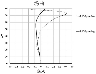
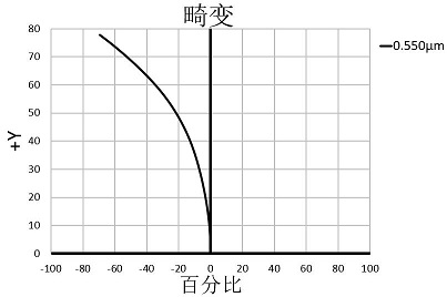
[0101] Depend on Figure 7 , 8 , 9, and 10, it can be seen that the field curvature of the meridional image plane and the sagittal image plane of this embodiment are both less than 0.6mm, the distortion is less than 79%, the chromatic aberration of the point spherical aberration on the axis is less than 0.12mm, and the lateral chromatic aber...

Embodiment 3

[0103] Figure 11 A schematic structural diagram of an optical imaging lens according to Embodiment 3 of the present application is shown. The structure of the optical imaging lens in this embodiment is roughly the same as that in Embodiment 1, except that the radius of curvature and material selection of each lens are different.

[0104] The relevant parameters of each lens of the optical imaging lens provided in this embodiment are shown in Table 5.

[0105] table 5

[0106]

[0107] The surface coefficients of each aspheric surface of the optical imaging lens in this embodiment are shown in Table 6.

[0108] Table 6

[0109]

[0110] Depend on Figure 12 , 13 , 14, and 15, it can be seen that the field curvature of the meridional image plane and the sagittal image plane of this embodiment are both less than 1.9mm, the distortion is less than 77%, the axial point spherical aberration chromatic aberration is less than 0.11mm, and the lateral chromatic aberration is...


PUM


Abstract

The invention discloses an optical imaging lens. The lens sequentially comprises a first lens, a second lens, a third lens, a fourth lens, a fifth lens, a sixth lens and a seventh lens from an object side to an image side along an optical axis. The first lens has negative focal power, the object side surface of the first lens is a convex surface, and the image side surface of the first lens is a concave surface; the second lens has positive focal power, the object side surface of the second lens is a convex surface, and the image side surface of the second lens is a concave surface; the third lens has positive focal power, the object side surface of the third lens is a convex surface, and the image side surface of the third lens is a convex surface; the fourth lens has positive focal power, the object side surface of the fourth lens is a convex surface, and the image side surface of the fourth lens is a convex surface; the fifth lens has negative focal power, the object side surface of the fifth lens is a convex surface, and the image side surface of the fifth lens is a concave surface; the sixth lens has positive focal power, the object side surface of the sixth lens is a convex surface, and the image side surface of the sixth lens is a convex surface; the seventh lens element with negative refractive power, the object side surface of the seventh lens is a concave surface, and the image side surface of the seventh lens is a concave surface;, wherein the effective focal length f1 of the first lens and the total effective focal length f of the optical imaging lens satisfy the following relational expression: -1.5<f1 / f<-0.8.

Description

technical field [0001] The present invention relates to an optical imaging lens, more particularly, to an optical imaging lens including seven lenses. Background technique [0002] In recent years, with the rapid upgrading of portable electronic devices such as smartphones and tablet computers, the market has higher and higher requirements for product-side camera lenses. However, when pursuing high-quality photos, it is often affected by the thinner and lighter requirements of mobile phones and the limitation of the total length of the lens. Therefore, how to design an optical imaging lens with excellent imaging quality and conforming to the characteristics of thinness, lightness and compactness has always been our goal. Contents of the invention [0003] Based on this, the object of the present invention is to provide an optical imaging lens that is applicable to portable electronic devices and has at least one of the advantages of ultra-wide angle, high pixel and small ...

Claims


Application Information

Patent Timeline
Patent Type & Authority Applications(China)
IPC IPC(8): G02B13/00G02B13/18G02B13/06
CPCG02B13/0045G02B13/18G02B13/06
Inventor 刘绪明王义龙曾昊杰曾吉勇
Owner JIANGXI LIANYI OPTICS CO LTD
Why Eureka
Try Eureka