Radio frequency receiving circuit, radio frequency signal receiving method and device and electronic equipment

A technology of radio frequency reception and electronic equipment, which is applied in the field of communication and can solve problems such as low signal reception efficiency

Active Publication Date: 2021-04-06
VIVO MOBILE COMM CO LTD
View PDF14 Cites 3 Cited by
  • Summary
  • Abstract
  • Description
  • Claims
  • Application Information

AI Technical Summary

Problems solved by technology

[0006] The purpose of the embodiments of the present application is to provide a radio frequency receiving circuit, a radio frequency signal receiving method, device and electronic equipment, which can solve the problem that signals of the same frequency or similar frequency bands will appear when the electronic equipment receives signals of the same frequency or similar frequency bands at the same time. Competing for the low-noise amplifier connected to the shared single-pole multi-throw switch, resulting in low signal reception efficiency

Method used


Image

  • Radio frequency receiving circuit, radio frequency signal receiving method and device and electronic equipment
  • Radio frequency receiving circuit, radio frequency signal receiving method and device and electronic equipment
  • Radio frequency receiving circuit, radio frequency signal receiving method and device and electronic equipment

Examples


Embodiment Construction

[0033] The following will clearly and completely describe the technical solutions in the embodiments of the present application with reference to the drawings in the embodiments of the present application. Obviously, the described embodiments are part of the embodiments of the present application, not all of them. Based on the embodiments in this application, all other embodiments obtained by persons of ordinary skill in the art without creative efforts fall within the protection scope of this application.

[0034] The terms "first", "second" and the like in the specification and claims of the present application are used to distinguish similar objects, and are not used to describe a specific sequence or sequence. It should be understood that the terms so used are interchangeable under appropriate circumstances such that the embodiments of the application can be practiced in sequences other than those illustrated or described herein, and that references to "first," "second," et...


PUM


Abstract

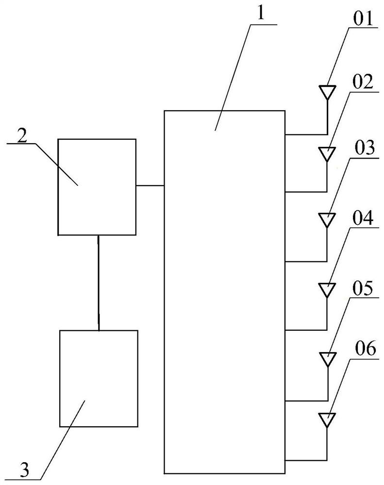
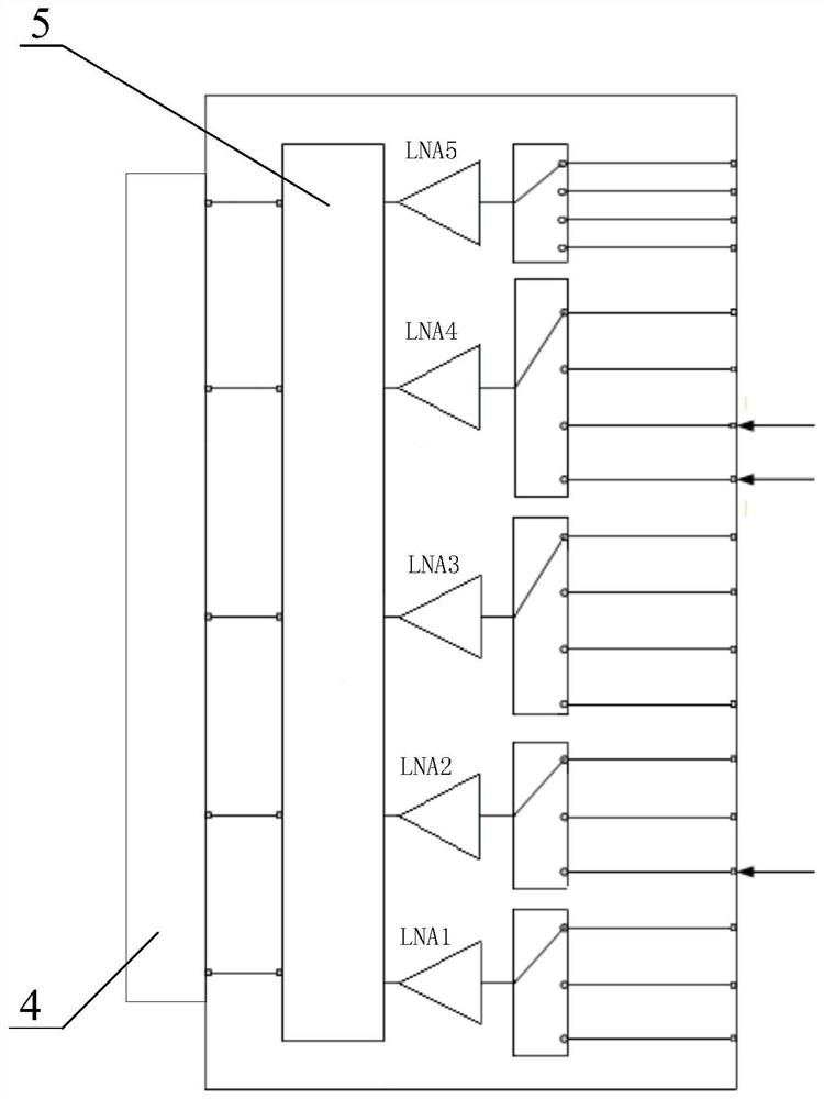
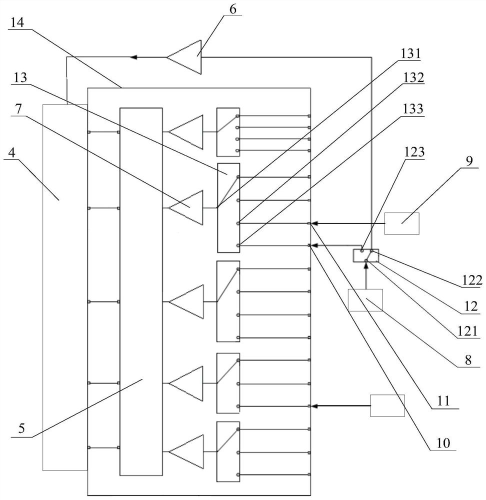
The invention discloses a radio frequency receiving circuit, a radio frequency signal receiving method and device and electronic equipment, and relates to the technical field of communication. The radio frequency receiving circuit comprises a first low-noise amplifier, a second low-noise amplifier, a switch module, a first antenna, a second antenna and a controller, the controller is connected with the first ends of the first low-noise amplifier and the second low-noise amplifier, the first end of the switch module is connected with the second ends of the first low-noise amplifier and the second low-noise amplifier, and the second end of the switch module is connected with the first antenna and the second antenna; when the switch module is in a first state, the first low-noise amplifier is communicated with the first antenna, and the second low-noise amplifier is communicated with the second antenna; and when the switch module is in the second state, the second low-noise amplifier is communicated with the first antenna or the second antenna. The scheme provided by the invention is used for solving the problem that an antenna is idle due to the fact that a low-noise amplifier connected with a shared single-pole multi-throw switch is scrambled when signals of the same frequency band or similar frequency bands are received.

Description

technical field [0001] The present application belongs to the technical field of communication, and specifically relates to a radio frequency receiving circuit, a radio frequency signal receiving method, device and electronic equipment. Background technique [0002] The fifth-generation mobile communication technology, referred to as 5G, is advancing at a high speed. 5G introduces new broadband spectrum, such as the millimeter wave frequency band, and the frequency band below 6G (sub 6G for short) is divided into 3.5GHz (range 3.3GHz-4.2GHz) and 4.5GHz (range 4.4GHz-5.0GHz) frequency band to achieve broadband high-speed and low-latency coverage requirements, while also using large-scale antenna technology and multiple access, beamforming, high-power terminal and other technologies Achieve high reliability and low latency to meet application requirements such as Internet of Vehicles, autonomous driving and telemedicine; support ultra-clear video applications with higher commu...

Claims


Application Information

Patent Timeline
Patent Type & Authority Applications(China)
IPC IPC(8): H04B1/00H04B1/16H04W88/06
CPCH04B1/005H04B1/16H04W88/06Y02D30/70
Inventor 陈芳胜胡建
Owner VIVO MOBILE COMM CO LTD
Why Eureka
Try Eureka