Supercharge Your Innovation With Domain-Expert AI Agents!

Midwifery device for obstetrics and gynecology department

A technology of obstetrics and gynecology, pulling force, applied in the field of medical devices, can solve the problems of large volume, difficult to determine the position, easy to side slip, etc., to avoid inaccuracy, reduce damage, and avoid damage.

Pending Publication Date: 2021-04-09
济南市章丘区中医医院
View PDF18 Cites 0 Cited by
  • Summary
  • Abstract
  • Description
  • Claims
  • Application Information

AI Technical Summary

Problems solved by technology

Although the scheme of using air pressure to increase the pinching force can reduce the pain of the puerpera, it is bulky and also easy to slip; it is difficult to determine the position of the forceps during use

Method used


Image

  • Midwifery device for obstetrics and gynecology department
  • Midwifery device for obstetrics and gynecology department
  • Midwifery device for obstetrics and gynecology department

Examples


Embodiment 1

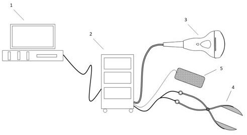
[0028] This embodiment introduces the specific structure of the present invention. combine Figure 1-3 , a kind of obstetrics and gynecology midwifery device of the present invention, comprises control computer 1, main control cabinet 2, ultrasonic probe 3, pressure regulating forceps 4 and tension detector 5; Computer connects main control cabinet 2, and main control cabinet 2 connects respectively , an ultrasonic probe 3, a pressure-regulating forceps 4 and a tension detector 5; the main control cabinet 2 is provided with a pressure-regulating air pump, an ultrasonic transceiver driver, and a tension detection controller;

[0029] The ultrasonic probe 3 is connected to the ultrasonic transceiver driver, and the ultrasonic transceiver driver displays the detection image of the ultrasonic probe 3 on the display screen of the control computer 1 in real time; Controlled by a pressure-regulating air pump; the tension detection controller is connected to the tension detector 5, w...

Embodiment 2

[0045] This embodiment introduces the usage method of the device of the present invention.

[0046] During delivery, when forceps are needed, turn on the computer of the midwifery device, the main control cabinet, the ultrasonic probe, the pressure-regulating forceps and the tension detector.

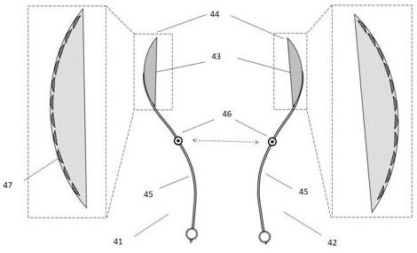
[0047] Use the second frequency of the ultrasound probe to image the fetus inside the uterus, observe the fetal position on the computer screen, and use the first frequency of the ultrasound probe to prepare for imaging the pressure regulating forceps and the suction cups on the forceps. Put the first forceps of the pressure-regulating forceps into the birth canal, observe and adjust the position of the pressure-regulating forceps through the imaging of the ultrasonic probe on the computer, so that the contact plate of the pressure-regulating forceps fits the fetal skin and avoids the facial features of the fetus; Then put the second forceps into the birth canal, and adjust the position...


PUM


Abstract

The invention relates to a midwifery device for the obstetrics and gynecology department. The midwifery device comprises a control computer, a main control cabinet, an ultrasonic probe, pressure regulating obstetric forceps and a tension detector, wherein the computer is connected with the main control cabinet, and the main control cabinet is connected with the ultrasonic probe, the pressure regulating obstetric forceps and the tension detector separately; and the main control cabinet is provided with a pressure regulating air pump, an ultrasonic receiving and transmitting driver and a tension detection controller. Small suction cups different in size are arranged on the pressure regulating obstetric forceps, the suction power of the suction cups can be adjusted through the computer according to specific conditions, thus the harm of the obstetric forceps to a fetus is reduced, and safe delivery of the fetus is guaranteed; and when the obstetric forceps are put in, the position of the obstetric forceps is determined through ultrasonic detection, the suction cups can be precisely attached to the skin of the fetus in a sucking manner, the inaccuracy of hand touch is avoided, and the situation that the suction cups are attached to suck the ears, the nose, the eyes and the like of the fetus to cause harm is also avoided.

Description

technical field [0001] The invention relates to the field of medical devices, in particular to a midwifery device for obstetrics and gynecology. Background technique [0002] Forceps delivery is surgery in which forceps are used to pull the fetal head to help the fetus out. According to the position of the fetal head in the pelvic cavity when the forceps are placed, it can be divided into: ① low forceps, which means that the bony part of the fetal head has reached the pelvic floor, and the sagittal suture is on the anteroposterior diameter of the pelvic outlet. ② Median forceps, refers to the fetal head biparietal diameter has passed the pelvic entrance, but has not reached the pelvic floor. ③ High forceps, refers to the fetal head has not been connected, that is, the biparietal diameter does not pass the pelvic entrance. Low forceps are more commonly used. [0003] Application number: 201910295128.8 discloses a non-invasive obstetric forceps, including a forceps handle, ...

Claims


Application Information

Patent Timeline
Patent Type & Authority Applications(China)
IPC IPC(8): A61B17/44A61B8/08A61B34/20A61B90/00
CPCA61B17/442A61B8/0866A61B8/0841A61B34/20A61B90/06A61B2017/445A61B2017/447A61B2017/00017A61B2017/00106A61B2034/2063A61B2034/2065
Inventor 张哲李晨阳雷小雨
Owner 济南市章丘区中医医院
Features
  • R&D
  • Intellectual Property
  • Life Sciences
  • Materials
  • Tech Scout
  • Unparalleled Data Quality
  • Higher Quality Content
  • 60% Fewer Hallucinations
Learn More