Lying type medical injection positioning system

A positioning system and flat-laying technology, applied in the field of medical devices, can solve problems such as inconvenient injections

Inactive Publication Date: 2021-04-09
周春芳
View PDF9 Cites 0 Cited by
  • Summary
  • Abstract
  • Description
  • Claims
  • Application Information

AI Technical Summary

Problems solved by technology

[0003] Aiming at the deficiencies of the prior art, the present invention provides a flat medical injection positioning system, which solves the problem that the traditional syringe needs to be hand-held by the user for injection, and it is very inconvenient for the user to inject himself.

Method used


Image

  • Lying type medical injection positioning system
  • Lying type medical injection positioning system
  • Lying type medical injection positioning system

Examples


Embodiment Construction

[0025] The following will clearly and completely describe the technical solutions in the embodiments of the present invention with reference to the accompanying drawings in the embodiments of the present invention. Obviously, the described embodiments are only some, not all, embodiments of the present invention. Based on the embodiments of the present invention, all other embodiments obtained by persons of ordinary skill in the art without making creative efforts belong to the protection scope of the present invention.

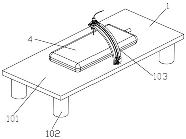
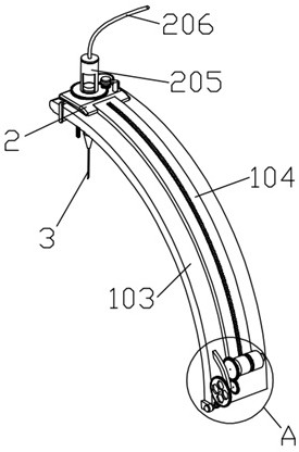
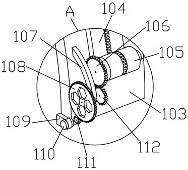
[0026] see figure 1 , figure 2 , image 3 , Figure 4 , Figure 5 , Figure 6 , Figure 7 , Figure 8 , Figure 9 As shown, the present invention provides a technical solution: a flat medical injection positioning system, including an adjustment module 1, an auxiliary module 2, an injection module 3 and an airbag 4, such as image 3 and Figure 7 It is a structural diagram of the adjustment module of the present invention, wherein the adjustment modu...


PUM


Abstract

The invention discloses a lying type medical injection positioning system which comprises an adjusting module, an auxiliary module, an injection module and an air bag. By arranging the adjusting module, the distance between the bottom end of a needle tube and the skin of a patient can be adjusted, so that the user can be helped to inject for himself / herself; and by arranging the auxiliary module and the injection module, when the needle tube is inserted into the skin, the pricking feeling of the skin because of the needle tube can be reduced by rotating an injection tube and the needle tube.

Description

technical field [0001] The invention relates to the technical field of medical devices, in particular to a lying flat medical injection positioning system. Background technique [0002] The emergence of syringes is an epoch-making revolution in the field of medical appliances. The process of withdrawing and injecting gas or liquid with a needle is called injection. The syringe consists of a syringe with a small hole at the front end and a matching piston core rod, which is used to inject a small amount of liquid or inject it into areas that are inaccessible by other methods or withdraw it from those places. When the core rod is pulled out, the liquid Or the gas is inhaled from the small hole at the front end of the syringe, and the liquid or gas is squeezed out when the core rod is pushed in. The traditional syringe requires the user to hold the injection, which is very inconvenient when the user injects himself. Contents of the invention [0003] Aiming at the deficienc...

Claims


Application Information

Patent Timeline
Patent Type & Authority Applications(China)
IPC IPC(8): A61G13/00A61G13/10A61G13/12A61M5/20A61M5/31
CPCA61G13/00A61G13/10A61G13/1265A61M5/20A61M5/31A61M2005/2006A61M2005/2026A61M2005/206
Inventor 周春芳
Owner 周春芳
Why Eureka
Try Eureka