Lifting type new energy automobile charging pile

A technology of new energy vehicles and charging piles, applied in electric vehicle charging technology, charging stations, electric vehicles, etc., can solve the problems of charging pile shell deformation, charging chip extrusion damage, etc., and achieve the effect of improving stability

Inactive Publication Date: 2021-04-09
鲍雪花
View PDF0 Cites 0 Cited by
  • Summary
  • Abstract
  • Description
  • Claims
  • Application Information

AI Technical Summary

Problems solved by technology

[0003] The structure of common new energy vehicle charging piles is usually located above the ground. When the vehicle is parked, the vehicle is likely to directly collide with the car charging pile. The main charging component of the car charging pile is the charging chip, which is located in the charging pile. Inside the shell, the shell of the charging pile is generally made of thin plastic material. Once the car squeezes and collides with the shell of the charging pile, the shell of the charging pile is easily deformed, thereby causing crush damage to the internal charging chip.

Method used


Image

  • Lifting type new energy automobile charging pile
  • Lifting type new energy automobile charging pile
  • Lifting type new energy automobile charging pile

Examples


Embodiment Construction

[0037] The following is attached figure 1 - attached image 3 , the specific implementation manner of the present invention will be further described in detail, so as to make the technical solution of the present invention easier to understand and grasp.

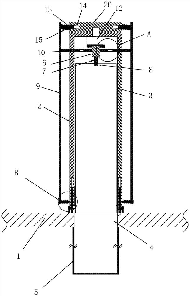
[0038] A lifting type new energy vehicle charging pile includes a charging pile casing 2 installed above the ground 1, and a charging chip 3 is arranged inside the charging pile casing 2.

[0039] A driving motor 12 is installed inside the charging pile casing 2, and the driving motor 12 is located close to the upper end of the charging pile casing 2. The output shaft of the driving motor 12 vertically penetrates the upper end surface of the charging pile casing 2, and the upper A turntable 26 is installed on the end face, and the turntable 26 is arranged horizontally.

[0040] There are a number of trigger pieces 9 evenly distributed on the outside of the charging pile housing 2 , and the number of trigger pieces 9 are al...


PUM


Abstract

The invention provides a lifting type new energy automobile charging pile. The charging pile comprises a charging pile shell mounted above the ground, a charging chip is arranged in the charging pile shell, a descending groove is formed in the ground, the descending groove is used for being communicated with the interior of the charging pile shell, a material receiving bag made of an elastic material is arranged in the descending groove, and the charging chip can slide and fall into the material receiving bag of the descending groove from the interior of the charging pile shell; a sliding table is slidably connected into the charging pile shell, a first connecting piece is arranged on the sliding table, a second connecting piece is arranged on the charging chip, and the first connecting piece is connected with a second connecting piece; and a plurality of trigger pieces are arranged on the periphery of the charging pile shell, each trigger piece is correspondingly provided with a trigger rod, and the trigger rods penetrate through the charging pile shell and abut against the sliding table. When the outside is impacted, the charging chip in the charging pile can descend to the position below the ground, so that damage to the charging chip in the charging pile due to impact is reduced.

Description

technical field [0001] The present invention relates to a new energy vehicle charging pile, in particular to a lifting type new energy vehicle charging pile. Background technique [0002] The traditional new energy vehicle charging pile structure includes a charging pile casing installed on the ground, a charging chip is installed inside the charging pile casing, a charging connector is connected to the charging chip, and the charging connector is connected to the car charging port to charge the new energy vehicle. . [0003] The structure of common new energy vehicle charging piles is usually located above the ground. During the process of parking the vehicle, the vehicle is likely to directly collide with the car charging pile. The main charging component of the car charging pile is the charging chip, and the charging chip is located in the charging pile. Inside the shell, the shell of the charging pile is generally made of thin plastic material. Once the car squeezes and...

Claims


Application Information

Patent Timeline
Patent Type & Authority Applications(China)
IPC IPC(8): B60L53/31B60L53/30
CPCB60L53/30B60L53/31Y02T10/70Y02T10/7072Y02T90/12
Inventor 鲍雪花
Owner 鲍雪花
Why Eureka
Try Eureka