
Battery charging generator for vehicle

A generator and vehicle technology, applied in the direction of electrical components, electromechanical devices, electric components, etc., can solve the problems of multi-working hours, increase in the number of parts, increase the number of parts, etc., reduce the number of combined operations, reduce the number of parts, and reduce the number of parts Effect

Inactive Publication Date: 2003-10-29
MITSUBISHI ELECTRIC CORP
View PDF0 Cites 0 Cited by
  • Summary
  • Abstract
  • Description
  • Claims
  • Application Information

AI Technical Summary

Problems solved by technology

[0014] (1) The clutch housing 22 and the pulley 13 are separate structures, and the pulley is press-fitted to the clutch housing, so the number of parts increases, and many man-hours are required for the combined operation
Also, since the clutch housing is deformed at the same time as the press-fit operation, the accuracy of the roller fitting portion is reduced, resulting in a significant drop in quality
[0015] (2) After the clutch inner sleeve 21 has been assembled on the rotating shaft 8a, the nut 25 is used to prevent it from falling out, which also increases the number of parts and requires more man-hours for assembly
[0016] (3) There is no separate bearing between the clutch outer sleeve 22 and the inner sleeve 21
[0017] (4) The dustproof and waterproof performance of the clutch is not considered, so it is necessary to take measures for this

Method used


Image

  • Battery charging generator for vehicle
  • Battery charging generator for vehicle
  • Battery charging generator for vehicle

Examples


Embodiment 1

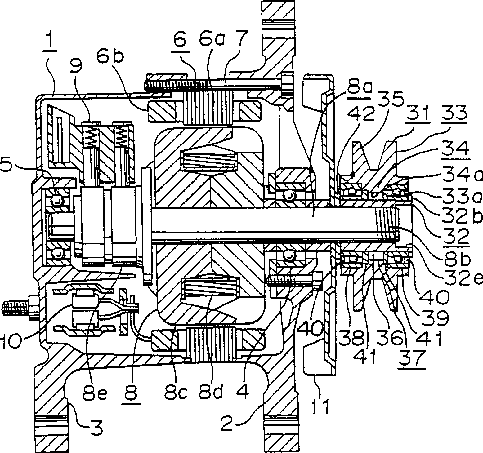
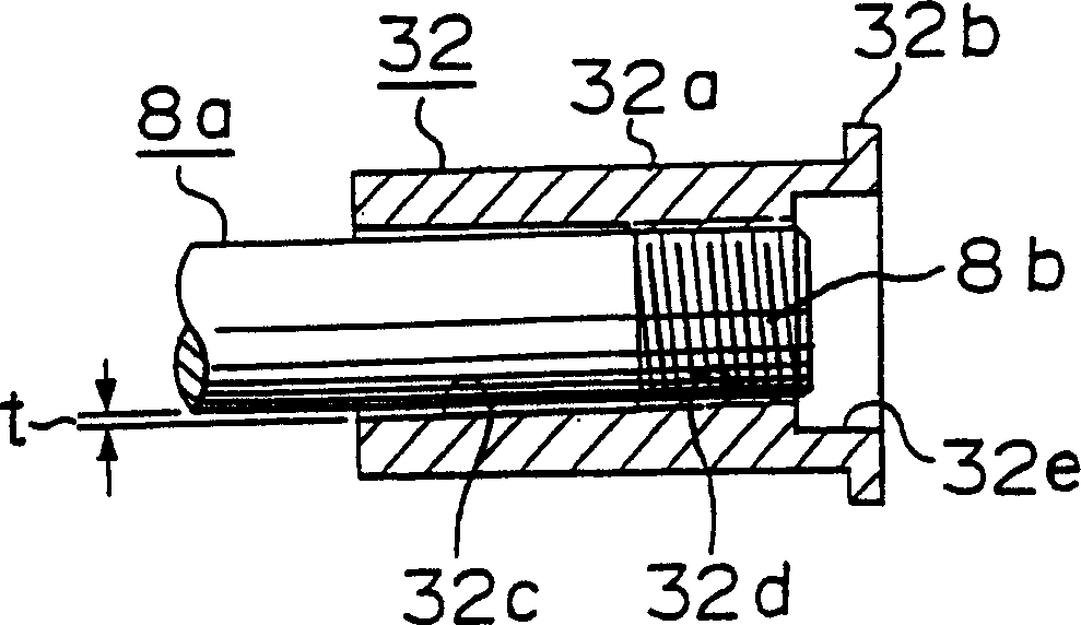
[0030] An embodiment of the present invention will be described below with reference to the drawings. figure 1 Is a view of the generator structure, figure 2 It is an enlarged view of the detailed structure of the inner sleeve of the one-way clutch. figure 1 with figure 2 In, the symbols 1 to 11 indicate the sum Figure 6 The same part as a traditional generator. Therefore, the corresponding parts use the same symbols, and the explanation is omitted in this article. However, the difference between this embodiment and the conventional example is that the rotor shaft 8a is shorter than that of a conventional generator, such as figure 1 Shown.

[0031] The number 31 is a one-way clutch, and its structure is as follows. 32 denotes a hollow cylindrical clutch inner sleeve, in which a flange 32b with a large outer diameter is provided at the right end of the outer circumferential portion 32a and constitutes a whole; such as figure 2 Shown. In addition, the right side of the hollow...

Embodiment 2

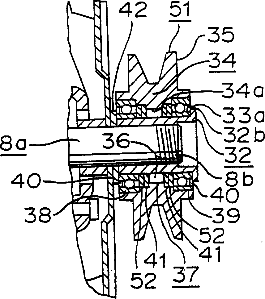
[0050] image 3 It is a structural view of another embodiment of the present invention. This embodiment will be explained below. Numeral 51 denotes a one-way clutch in which oil seals 52 are respectively installed between the ball bearings 38 and 39 and the engaging and disengaging parts 37 (clutch parts). Other structures and figure 1 The embodiment is the same.

[0051] The oil seal 52 separates the ball bearings 38 and 39 from the engaging and disengaging portion 37. In addition, considering the overall performance of the clutch, the rotating shaft 8a and the clutch inner sleeve 32 are installed with each other in a clearance fit. Therefore, this embodiment completely prevents the grease in the clutch components from flowing out of the gap, thereby achieving improved reliability.

[0052] In the case of using the oil seal 52, it is not necessary to pay special attention to the sealing performance between the bearing and the joining and separating parts. However, when differen...

Embodiment 3

[0055] Figure 4 It is a structural diagram of another embodiment of the present invention. In this embodiment, the rotor shaft also serves as a clutch inner sleeve. The structure is explained below.

[0056] The number 61 denotes a one-way clutch, in which the rotating shaft 62 also acts as the inner clutch 63. That is, the rotating shaft 62 has the function of the clutch inner sleeve 63. In this case, the rotating shaft 62 is provided with an external thread 62a, and the nut 64 is engaged with the external thread 62a. This method fastens the pulley with the one-way clutch to the rotating shaft 62. The material of the shaft 63 is forged steel. The part of the rotating shaft 63 facing the roller 36 on the outer circumference of the clutch inner sleeve 63 is induction hardened. Other structures and figure 1 The same as in Example 1.

[0057] By also serving as the rotating shaft 62 of the clutch inner sleeve 63, the deviation accuracy of the pulley 35 relative to the rotating shaf...


PUM


Abstract

The object of the present invention is to provide a generator with high productivity, low price and high durability. According to the vehicle charging generator equipped with a one-way clutch of the present invention, the clutch has a clutch inner sleeve and a clutch outer sleeve, the inner sleeve is installed on the rotor shaft, the outer sleeve is inserted between the inner sleeve and the pulley, and the pulley is driven by the power unit of the vehicle. It is driven and transmits power in only one direction of rotation from the pulley to the rotating shaft. It is characterized in that: there is an external thread on the shaft, and an internal thread is provided on the inner circumference of the inner sleeve of the clutch; through the engagement of the internal thread and the external thread, the The clutch inner sleeve is fixed to the shaft, and the clutch outer sleeve and the pulley are integrally formed. According to the vehicle charging generator of the present invention, fastening nuts are omitted to reduce the number of parts, and the combined operation steps are further reduced. Accordingly, combination operations are facilitated and overall accuracy is improved.

Description

Invention field [0001] The present invention relates to a vehicle charging generator with a one-way clutch. Background technique [0002] Figure 5 with 6 Represents a conventional vehicle charging generator (hereinafter referred to as generator). As an example, the generator is described in Japanese Unexamined Patent Publication No. 101353 / 1981, where Figure 5 Is the generator structure view, Figure 6 A partial enlarged view showing the structural details of the one-way clutch. in Figure 5 with Figure 6 Among them, the number 1 indicates the main body of the generator, and its composition is as follows: the number 2 represents the front support, the number 3 is the rear support, and the front bearing 4 and the rear bearing 5 are installed in the middle of the two supports. The number 6 refers to an armature having an armature core 6a and an armature coil 6b wound on the core 6a. Insert the armature iron core 6a between the two brackets, and fix the iron core in the Figure 5...

Claims


Application Information

Patent Timeline
Patent Type & Authority Patents(China)
IPC IPC(8): H02K7/18H02K7/10
CPCH02K7/1004H02K7/20
Inventor 善明敬策古西启一五十棲秀三森下暸
Owner MITSUBISHI ELECTRIC CORP
Learn More