

Fairing structure of medium-sized unmanned aerial vehicle with high lift-drag ratio
A high lift-to-drag ratio, fairing technology, applied in the field of drones, can solve problems affecting the flight effect and equipment of drones
- Summary
- Abstract
- Description
- Claims
- Application Information
AI Technical Summary
Problems solved by technology
Method used
Image

Examples
Embodiment 1
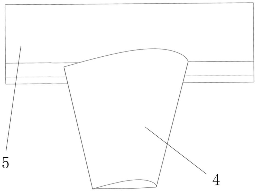
[0041] This embodiment provides a fairing structure for a medium-sized unmanned aerial vehicle with a high lift-to-drag ratio. The fairing structure is arranged at the wing root of the wing 4, connects the wing root and the fuselage 5, and adopts a small-angle chamfer For rectification, the angle between the fuselage and the wing is greater than 90°; the shape of the wing-body junction of the UAV is as follows figure 1 Shown (schematic diagram of wing structure without fairing);
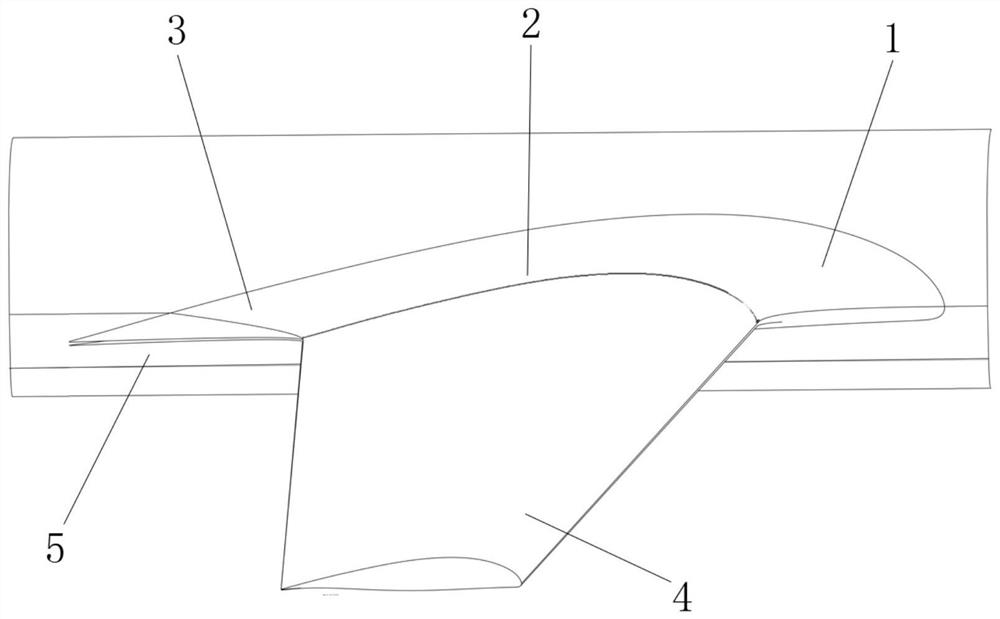
[0042] The fairing structure is as figure 2 Shown (rectification method 1), including:
[0043] Leading edge rectification structure 1, the leading edge rectifying structure is an arc structure; the leading edge sweep angle of the leading edge rectifying structure is 40°; the leading edge extension length is 370mm, the leading edge radius is 355mm, and the spanwise length is 300mm.
[0044] The spanwise rectification structure 2, the number of the spanwise rectification structure having profile t...
Embodiment 2
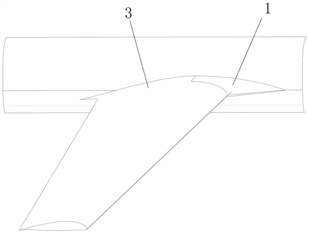
[0050] This embodiment provides a fairing structure for a medium-sized unmanned aerial vehicle with a high lift-to-drag ratio. The difference from Embodiment 1 is that it does not include a "span-wise rectifying structure"; image 3 As shown, including front rectification structure 1 and middle and rear rectification structure 3; (rectification mode 2)
[0051] Specifically, similar to wing strakes, the maximum thickness of the fairing does not exceed the maximum thickness of the largest airfoil at the wing root, and is only added before the maximum thickness of the wing, with a sharper leading edge shape, the purpose of which is The transition between the leading edge of the wing and the fuselage is smooth, and the boundary layer at the stagnation point of the leading edge is eliminated as much as possible to prevent the flow separation of the boundary layer caused by the sharp change of speed. Fairing form such as image 3 shown. The length of the front rectification area ...
PUM
 Abstract
Description
Claims
Application Information