
Unmanned aerial vehicle flight angle balancing device

A flight angle and UAV technology, applied in the field of UAV flight angle trimming devices, can solve the problems of unfavorable multi-angle comprehensive comparison, poor UAV fixation and adjustment stability, difficult UAV rotation angle adjustment, etc. Achieve the effect of multi-angle comprehensive comparison, accurate flight angle trim, and stable rotation adjustment.

Pending Publication Date: 2021-04-09
陆颖怡
View PDF7 Cites 1 Cited by
  • Summary
  • Abstract
  • Description
  • Claims
  • Application Information

AI Technical Summary

Problems solved by technology

[0005] In order to solve the above technical problems, the present invention provides a UAV flight angle trimming device to solve the following deficiencies in the actual use of the UAV flight angle trimming device, such as: the above-mentioned UAV flight angle trimming device When in use, the fixation and adjustment stability of the UAV is poor, which makes the UAV flight angle trim results prone to errors. Because it is difficult to adjust the rotation angle of the UAV, it is not conducive to multi-angle comprehensive comparison, and cannot satisfy UAVs with different wing lengths are used in balance, resulting in low utilization of equipment

Method used


Image

  • Unmanned aerial vehicle flight angle balancing device
  • Unmanned aerial vehicle flight angle balancing device
  • Unmanned aerial vehicle flight angle balancing device

Examples


Embodiment

[0035] as attached figure 1 to attach Figure 9 Shown:

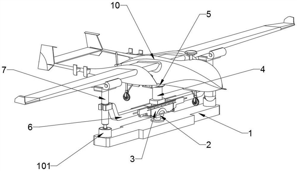
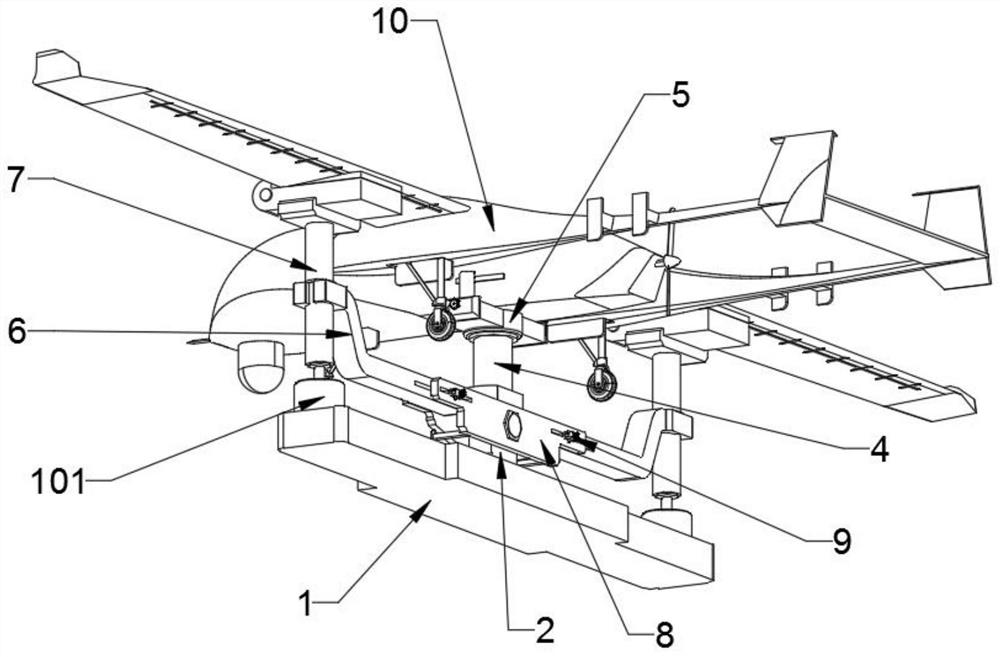
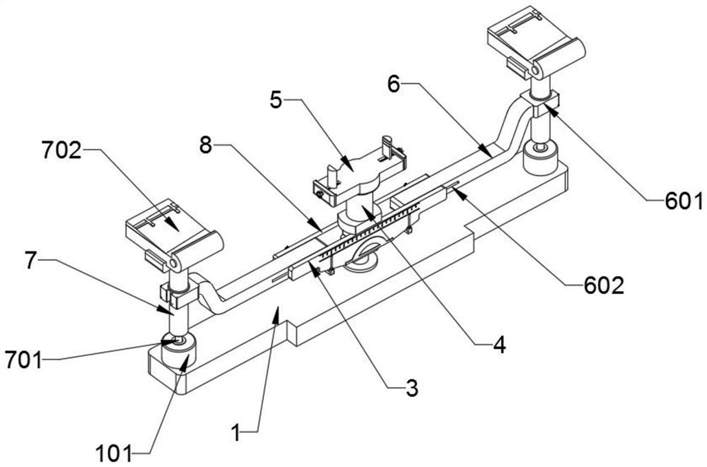
[0036] The invention provides a drone flight angle trimming device, which includes a base 1, a rotating seat 2 is fixedly installed in the middle of the top of the base 1; the rotating seat 2 includes a U-shaped sleeve 201, a shaft sleeve 202 and a locking bolt 203, 201 is provided with a shaft sleeve 202 inside, and the shaft sleeve 202 is rotationally connected with the U-shaped sleeve 201, and is controlled by a locking bolt 203; the base 1 includes a sleeve 101, and the left and right sides of the top of the base 1 are provided with sleeves 101, and two The sleeves 101 are distributed in a symmetrical manner; the front end of the rotating seat 2 is provided with a scale plate 3; the rear end of the rotating seat 2 is provided with a back plate 8, and the back plate 8 and the scale plate 3 are distributed in a parallel manner; the back plate 8 includes a pointer 801 and a limiter. Position slot 802, two pointers 801...


PUM


Abstract

The invention provides an unmanned aerial vehicle flight angle balancing device, relates to the technical field of unmanned aerial vehicle equipment, and aims at solving the problems that when the unmanned aerial vehicle flight angle balancing device is used, the stability of fixing and adjusting an unmanned aerial vehicle is poor, errors are likely to occur in the unmanned aerial vehicle flight angle balancing result. Because the unmanned aerial vehicle rotation angle is difficult to adjust, multi-angle comprehensive comparison is not facilitated. Furthermore the utilization rate of the equipment is low because balancing use of the unmanned aerial vehicles with different wing lengths cannot be satisfied. The unmanned aerial vehicle balancing device comprises a base, and a rotating seat is fixedly mounted in the middle of the top end of the base. The three arc-shaped grooves are formed in the bottom end of the bottom plate and distributed in an annular array mode, the arc-shaped grooves are slidably connected with the limiting column, the clamp and the unmanned aerial vehicle body are more convenient to install and connect, meanwhile, the clamp can be rotatably connected with the supporting column, and the rotating angle of the unmanned aerial vehicle body is convenient to adjust; the balancing process of the flight angle of the unmanned aerial vehicle is facilitated, and multi-angle comprehensive comparison is achieved.

Description

technical field [0001] The invention belongs to the technical field of unmanned aerial vehicle equipment, and more specifically relates to an unmanned aerial vehicle flight angle trimming device. Background technique [0002] Unmanned aircraft, referred to as "UAV", is an unmanned aircraft that is controlled by radio remote control equipment and its own program control device, or is completely or intermittently operated autonomously by an on-board computer. Compared with manned aircraft, drones are often more suitable for tasks that are too "dull, dirty or dangerous". Currently, they are widely used in aerial photography, agriculture, power inspection, disaster relief, film and television shooting, and romance. The use of UAV itself has been expanded, and developed countries are also actively expanding industry applications and developing UAV technology. During the UAV flight test, when there is an error between the test parameters and the estimated parameters, it is necess...

Claims


Application Information

Patent Timeline
IPC IPC(8): B64F5/60
CPCB64F5/60Y02T50/40
Inventor 陆颖怡
Owner 陆颖怡
Learn More