Laser weapon light spot monitoring and tracking system

A laser weapon and tracking system technology, which is applied in the field of laser spot monitoring and tracking systems, can solve problems such as unproposed solutions, and achieve the effects of improving fluency, speeding up feature extraction, and good compatibility

Active Publication Date: 2021-04-09
北京航天飞腾装备技术有限责任公司
View PDF5 Cites 0 Cited by
  • Summary
  • Abstract
  • Description
  • Claims
  • Application Information

AI Technical Summary

Problems solved by technology

For the above problems, no effective solution has been proposed

Method used


Image

  • Laser weapon light spot monitoring and tracking system
  • Laser weapon light spot monitoring and tracking system
  • Laser weapon light spot monitoring and tracking system

Examples


Embodiment Construction

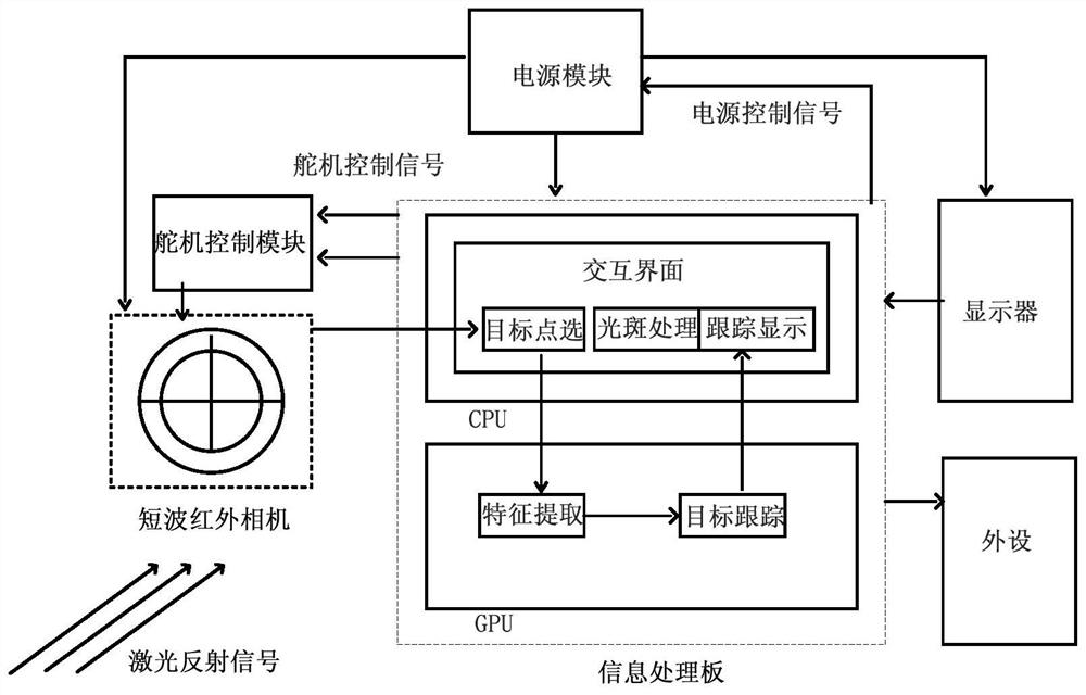
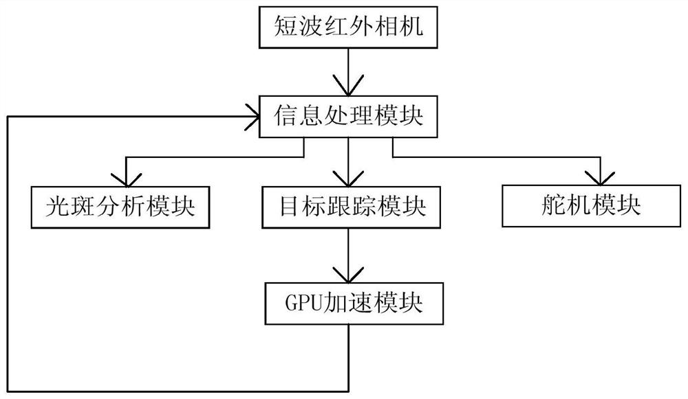
[0022] Such as figure 1 As shown, a laser weapon spot monitoring and tracking system of the present invention includes a short-wave infrared camera, an information processing board, a spot processing module, a target tracking module, a steering gear control module, and a power supply control module;

[0023] The short-wave infrared camera is used in conjunction with a fixed-focus lens; the short-wave infrared camera is used to image the 1064nm laser spot, and the exposure time and lens aperture of the camera are adjusted to make the camera image clear and the target outline visible to the naked eye; while monitoring the spot signal, the gray output to the information processing board in the form of a high-resolution image;

[0024] The information processing board receives the single-channel grayscale image output by the short-wave infrared camera through the network port, and displays the image through the display; selects the target image by using peripherals, and transfers ...


PUM


Abstract

The invention discloses a laser weapon light spot monitoring and tracking system, and the system comprises the steps: displaying a laser light spot, calculating the size of the light spot, and judging whether the laser light spot meets the irradiation requirements or not; when it is determined that the light spot meets the requirement, clicking an irradiation target, and tracking the position of the light spot; and evaluating the precision of the laser guided weapon according to the final position of the light spot. The technical problem of laser guided bomb precision evaluation in related technologies is solved, and the technical effects of being simple in structure, low in cost and high in portability are achieved.

Description

technical field [0001] The invention belongs to the field of guided weapon testing and relates to a laser spot monitoring and tracking system. Background technique [0002] Precision-guided weapons have become one of the indispensable strike means in today's information warfare, among which laser-guided weapons have become the weapons and equipment that various countries are vying to develop in recent years. Semi-active laser guidance technology is widely used in various conventional weapons such as missiles, rockets, and bombs because of its high strike accuracy, low cost, flexible operation, and simple structure. In the process of weapon performance testing and precision strikes, the weapon system needs the laser beam irradiated by the laser for guidance. The laser must first be irradiated on the target area. After diffuse reflection, the laser beam will reflect in all directions, and the seeker will receive the reflection. The laser energy can be used to determine the ta...

Claims


Application Information

Patent Timeline
Patent Type & Authority Applications(China)
IPC IPC(8): G01M11/02G06T7/66G06T7/73
CPCG01M11/0257G06T7/73G06T7/66G06T2207/10048
Inventor 任玮辰郭慧敏孟祥飞王河成宋敏吴德龙李天泽王怀野王冬岳峥
Owner 北京航天飞腾装备技术有限责任公司
Why Eureka
Try Eureka