Fixed subscriber unit of wireless local loop system
A technology of local loop and subscriber unit, applied in radio/induction link selection arrangement, wireless communication, line monitoring circuit, etc., can solve the problem of telephone pulse dialing signal being mistaken for hook signal and so on
- Summary
- Abstract
- Description
- Claims
- Application Information
AI Technical Summary
Problems solved by technology
Method used
Image
Examples
no. 1 example
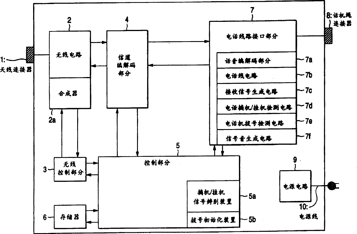
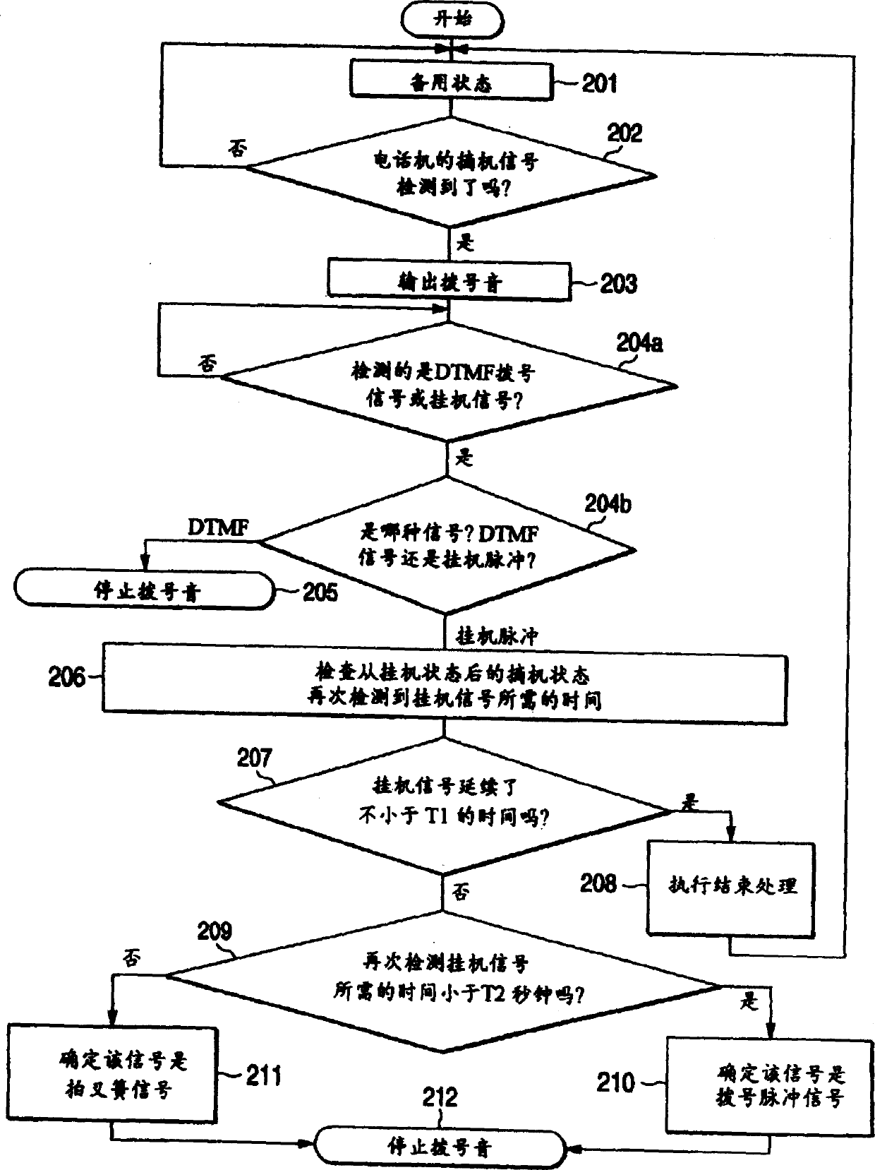
[0039] A first embodiment of the invention relates to a fixed subscriber unit provided with off-hook / on-hook signal discrimination means.
[0040] FIG. 1 is a block diagram showing the structure of a fixed subscriber unit (FSU) of a first embodiment of the present invention. In FIG. 1, reference numeral 1 denotes an antenna connector. Since the antenna of the FSU is generally installed outdoors, the antenna connector 1 is a connector for connecting the antenna cable. Reference numeral 2 denotes a radio circuit. The wireless circuit 2 transmits / receives wireless data while the frequency and transmission / reception time stamp are designated by the wireless control section 3 . Reference numeral 2a denotes a synthesizer built into the radio circuit. The synthesizer 2a generates a signal of a frequency selected by the wireless control section 3. The wireless control section 3 measures the received level from the wireless data received from the base station and writes the receive...
no. 2 example
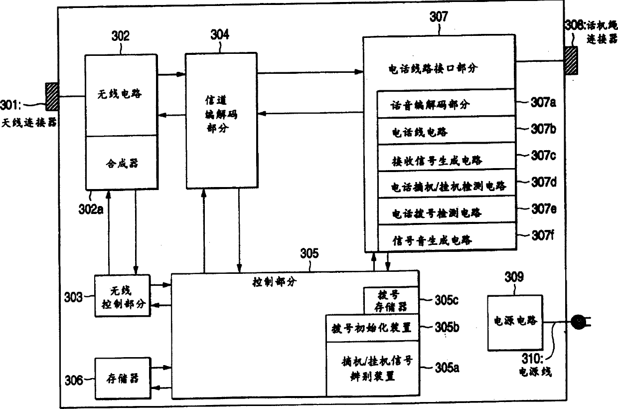
[0048] The second embodiment relates to a fixed subscriber unit that clears stored dial information and outputs a dial tone when a hook flash signal is detected during dialing.
[0049] FIG. 3 is a block diagram showing the structure of a fixed subscriber unit (FSU) of a second embodiment of the present invention. In FIG. 3, reference numeral 301 denotes an antenna connector. Since the antenna of the FSU is usually set outdoors, the antenna connector 301 is a connector for connecting the antenna cable. Reference numeral 302 denotes a radio circuit. Whereas the radio circuit 302 transmits / receives radio data frequencies and transmit / receive timings are specified by the radio control section 303, and reference numeral 302a denotes a synthesizer built into the radio circuit 302. The synthesizer 302 a generates a signal of a frequency specified by the wireless control section 303 . The wireless control section 303 measures the reception level based on the wireless data received...
no. 3 example
[0056] A third embodiment of the present invention relates to a fixed subscriber unit which outputs a dial tone to make a telephone set enter a dial input waiting state when a hook-flap signal is input during output of a busy tone or an alert tone.
[0057] FIG. 5 is a block diagram showing the structure of a fixed subscriber unit (FSU) of a third embodiment of the present invention. In FIG. 5, reference numeral 501 denotes an antenna connector. Since the antenna of the FSU is usually set outdoors, the antenna connector 501 is a connector for connecting an outdoor antenna cable. Reference numeral 502 denotes a wireless circuit. The wireless circuit 502 transmits / receives wireless data while the frequency and transmission / reception timing are designated by the wireless control section 503, and reference numeral 502a denotes a synthesizer within the wireless circuit 502. The synthesizer 502 a generates a signal of a frequency specified by the wireless control section 503 . Th...
PUM
 Abstract
Description
Claims
Application Information
 - R&D
- Intellectual Property
- Life Sciences
- Materials
- Tech Scout
- Unparalleled Data Quality
- Higher Quality Content
- 60% Fewer Hallucinations
Browse by: Latest US Patents, China's latest patents, Technical Efficacy Thesaurus, Application Domain, Technology Topic, Popular Technical Reports.
© 2025 PatSnap. All rights reserved.Legal|Privacy policy|Modern Slavery Act Transparency Statement|Sitemap|About US| Contact US: help@patsnap.com


