Bus bridge and bus phase modulation method

A technology of busbar bridge and busbar, which is applied in the direction of busbar/line arrangement, fully enclosed busbar device, etc., and can solve the problems of phase sequence mismatch and so on

Active Publication Date: 2021-04-09
HENAN SENYUAN ELECTRIC CO LTD
View PDF13 Cites 0 Cited by
  • Summary
  • Abstract
  • Description
  • Claims
  • Application Information

AI Technical Summary

Problems solved by technology

[0005] The purpose of the present invention is to provide a busbar bridge, which can connect the three-phase busbars of the switchgear correspon

Method used


Image

  • Bus bridge and bus phase modulation method
  • Bus bridge and bus phase modulation method
  • Bus bridge and bus phase modulation method

Examples


Embodiment 1

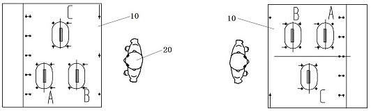
[0056] Embodiment 1 of the bus bridge: The bus bridge is used to connect two switch cabinets. The switch cabinets in this embodiment are arranged in a "face-to-face" manner. Font layout. When arranged in a "face-to-face" manner, the three-phase busbar terminal will appear figure 1 situation shown in . When the bus bridge in this embodiment connects two switch cabinets, A, B, and C of the two switch cabinets are connected in three phases through the connecting bus inside the bus bridge.

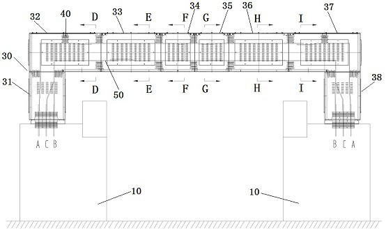
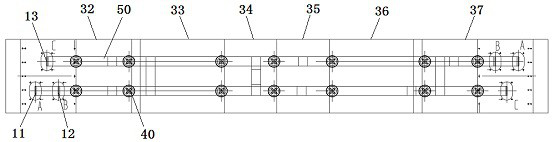
[0057] Such as figure 2 As shown, the bus bridge 30 is U-shaped as a whole, and its two ends are respectively connected to the tops of the two switch cabinets 10 . The busbar bridge 30 includes an axle housing. The inner wall of the axle housing is connected with an insulating support 40 as a supporting body by bolts. The insulating support 40 is a common insulating component in the prior art. The end is provided with a conductor and the surrounding surface is provided with an umbrella ski...

Embodiment 2

[0070] Such as Figure 10 and Figure 11 As shown, it is Embodiment 2 of the bus bridge in the present invention: the difference from the above-mentioned embodiments is that the type of switchgear to be adapted is different, and the arrangement of the supporting body in the axle housing of the bus bridge will also change accordingly. Such as Figure 13 As shown, in this embodiment, the switchgear is arranged in a "face-to-face" manner, and the top of the switchgear is provided with an A-phase bus terminal 11, a B-phase bus terminal 12, and a C-phase bus terminal 13. arranged in a manner.

[0071] The busbar bridge in this embodiment is U-shaped as a whole, and its two ends are respectively connected to the tops of the two switch cabinets. The busbar bridge includes an axle housing, and the inner wall of the axle housing is connected with an insulating support as a supporting body by bolts. The insulating support is a common insulating component in the prior art, with a cond...

Embodiment 3

[0084] Embodiment 3 of the busbar bridge in the present invention: the difference from the above embodiment is that in this embodiment, two sets of support bodies are connected to the bottom wall or top of the axle housing at the same time, and the support heights of the two sets of support bodies are different, so that The corresponding three-phase connection buses are staggered in the vertical direction, thereby being divided into two layers in the vertical direction.

[0085] Embodiment 4 of the busbar bridge in the present invention: the difference from the above embodiment is that in this embodiment, two sets of support bodies are arranged and connected on the left inner wall and the right inner wall of the axle housing, and each support body is L-shaped , so that the three-phase connecting bus is still divided into upper and lower layers in the axle housing.

[0086] Embodiment 5 of the bus bridge in the present invention: the difference from the above embodiments is tha...


PUM


Abstract

The invention provides a bus bridge and a bus phase modulation method, which can correspondingly connect three phases of buses of a switch cabinet so as to solve the problem of phase sequence non-correspondence when the switch cabinet is arranged in a face-to-face manner in the prior art. The bus bridge comprises a bridge shell, two sets of supporting bodies used for dividing a three-phase bus into two layers are arranged in the bridge shell, and the supporting bodies are used for supporting the bus connected between two switch cabinets. Each group of supporting bodies comprises supporting body matrixes arranged side by side, at least one of the supporting bodies of each supporting body matrix can form a phase modulation supporting body, and the phase modulation supporting body is used for enabling a bus to jump to other supporting body matrixes so as to realize adjustment of the trend of the bus; and the phase modulation supporting bodies in each supporting body matrix are staggered in the wiring direction.

Description

technical field [0001] The invention relates to a bus bridge and a bus phase modulation method. Background technique [0002] In the prior art, most of the switchgears are arranged in two or more rows, and each row of switchgears adopts the arrangement in which the front and the front face each other, that is, the "face-to-face" arrangement. There is a channel for the operator to enter and exit, so that the operator can operate the adjacent two rows of switch cabinets in the channel. [0003] Such as figure 1 As shown, it is an arrangement structure of a switchgear with three-phase busbars arranged in the shape of a character. For the same switchgear, the arrangement of the three-phase busbars on the top is also the same. When the operator 20 faces the switchgear 10 on the left side of the figure , phase A and B of the three-phase bus are located on the left hand side of the operator 20, and phase C is located on the right hand side of the operator 20; when the operator 20...

Claims


Application Information

Patent Timeline
IPC IPC(8): H02B1/22H02G5/06
CPCH02B1/22H02G5/06
Inventor 刘伟浩岳朝鹏李晖贾华雨王晓锋张雪鹏
Owner HENAN SENYUAN ELECTRIC CO LTD
Why Eureka
Try Eureka