Charger with automatic rotating shaft

A charger and shaft technology, applied in the field of chargers with automatic shafts, can solve the problems of inconvenient and stable adjustment of the charging port, affecting the convenience of charging applications, etc.

Active Publication Date: 2021-04-09
ASAP TECH (JIANGXI) CO LTD
View PDF4 Cites 4 Cited by
  • Summary
  • Abstract
  • Description
  • Claims
  • Application Information

AI Technical Summary

Problems solved by technology

[0003]Existing car chargers are not convenient for stably adjusting the orientation of the ch

Method used


Image

  • Charger with automatic rotating shaft
  • Charger with automatic rotating shaft
  • Charger with automatic rotating shaft

Examples


Embodiment 1

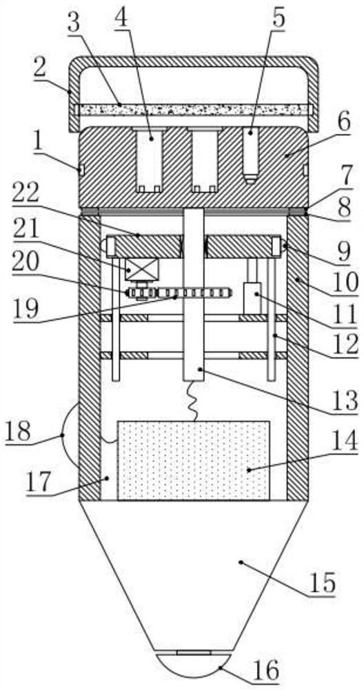
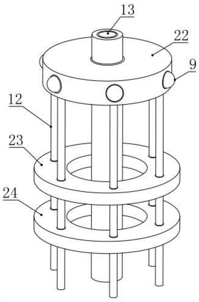
[0022] see Figure 1-2 , in an embodiment of the present invention, a charger with an automatic rotating shaft includes a charging body 6 and a charging head 10, the charging body 6 is co-located on the top of the charging head 10, and the charging body 6 is respectively provided with The USB interface 4 and the earphone charging port 5, the charging head 10 is provided with an installation cavity 17 with an upper opening, and a circuit board 14 is installed at the bottom of the installation cavity 17, and the circuit board 14 is electrically connected to the USB interface 4 and the earphone charging port 5 respectively. connection, the bottom of the charging head 10 is also equipped with a conical plug 15, the bottom of the conical plug 15 is equipped with a positive contact cap 16, and the lower side of the charging head 10 is also equipped with a negative contact 18, and the positive Both the contact cap 16 and the negative electrode contact 18 are electrically connected to...

Embodiment 2

[0026] see Figure 1-3 , the difference between this embodiment and embodiment 1 is:

[0027] In this embodiment, the charging body 6 and the charging head 10 are both cylindrical structures, and the bottom outer ring of the charging body 6 is provided with a first annular sealing ring 7, and the top outer ring of the charging head 10 is provided with The second annular sealing ring 8 vertically corresponding to the first annular sealing ring 7, through the setting of the first annular sealing ring 7 and the second annular sealing ring 8, can improve the sealing performance of the connection between the charging body 6 and the charging head 10, And after the charging body 6 and the charging head 10 are brought into contact, the charging body 6 is prevented from rotating.

[0028] The USB interface 4 can be a USB-B charging port, a Type-c charging port, or a Lightning charging port.

[0029] The charging body 6 can also be detachably covered with a sealing cover 2, the inner ...


PUM


Abstract

The invention relates to a vehicle-mounted charger, and concretely relates to a charger with an automatic rotating shaft. The charger comprises a charging body and a charging head part, the charging body is arranged at the top of the charging head part in a matching way, a central pipe is fixedly arranged in the middle of the bottom of the charging body, and an installation disc is rotationally arranged on the central pipe; a driving mechanism used for driving the central pipe to rotate is further installed on the lower side of the installation disc, a plurality of guide rods are fixedly installed on the outer ring of the lower side of the installation disc in the circumferential direction, an upper guide plate and a lower guide plate are fixedly installed in the installation cavity below the installation disc, and the guide rods are in sliding connection with the upper guide plate and the lower guide plate in a matched mode; and a telescopic cylinder used for controlling the installation disc to ascend and descend is further fixedly installed on the upper guide plate, and the driving mechanism and the telescopic cylinder are electrically connected with the circuit board. The orientation of a charging port can be conveniently and stably adjusted, the charging application convenience is improved, and the device is worthy of popularization.

Description

technical field [0001] The invention relates to a vehicle charger, in particular to a charger with an automatic rotating shaft. Background technique [0002] On-board charger refers to the on-board charger that is usually powered by car batteries (12V for cars; 24V for trucks), and is widely used in the field of lithium battery charging for various portable and handheld devices. Such as: mobile phone, PDA, GPS, etc. [0003] The existing on-board chargers are not convenient for stably adjusting the orientation of the charging port, which affects the convenience of charging applications and has great limitations. Therefore, in view of the above current situation, it is urgent to develop a charger with an automatic rotating shaft to overcome the deficiencies in current practical applications. Contents of the invention [0004] The purpose of the embodiments of the present invention is to provide a charger with an automatic rotating shaft, so as to solve the problems raised...

Claims


Application Information

Patent Timeline
IPC IPC(8): H02J7/00H01R35/00H01R13/629H01R13/627
CPCH02J7/0045H01R35/00H01R13/627H01R13/629
Inventor 罗冬华郑志华余超刘江博
Owner ASAP TECH (JIANGXI) CO LTD
Why Eureka
Try Eureka