Glass base plate box for liquid crystal display

A liquid crystal display, glass substrate technology, applied in instruments, nonlinear optics, packaging, etc., can solve problems such as substrate distortion

Inactive Publication Date: 2003-06-25
INNOLUX CORP
View PDF1 Cites 4 Cited by
  • Summary
  • Abstract
  • Description
  • Claims
  • Application Information

AI Technical Summary

Problems solved by technology

However, the glass substrate may also be inserted into the notch 26 b...

Method used


Image

  • Glass base plate box for liquid crystal display
  • Glass base plate box for liquid crystal display
  • Glass base plate box for liquid crystal display

Examples


Embodiment Construction

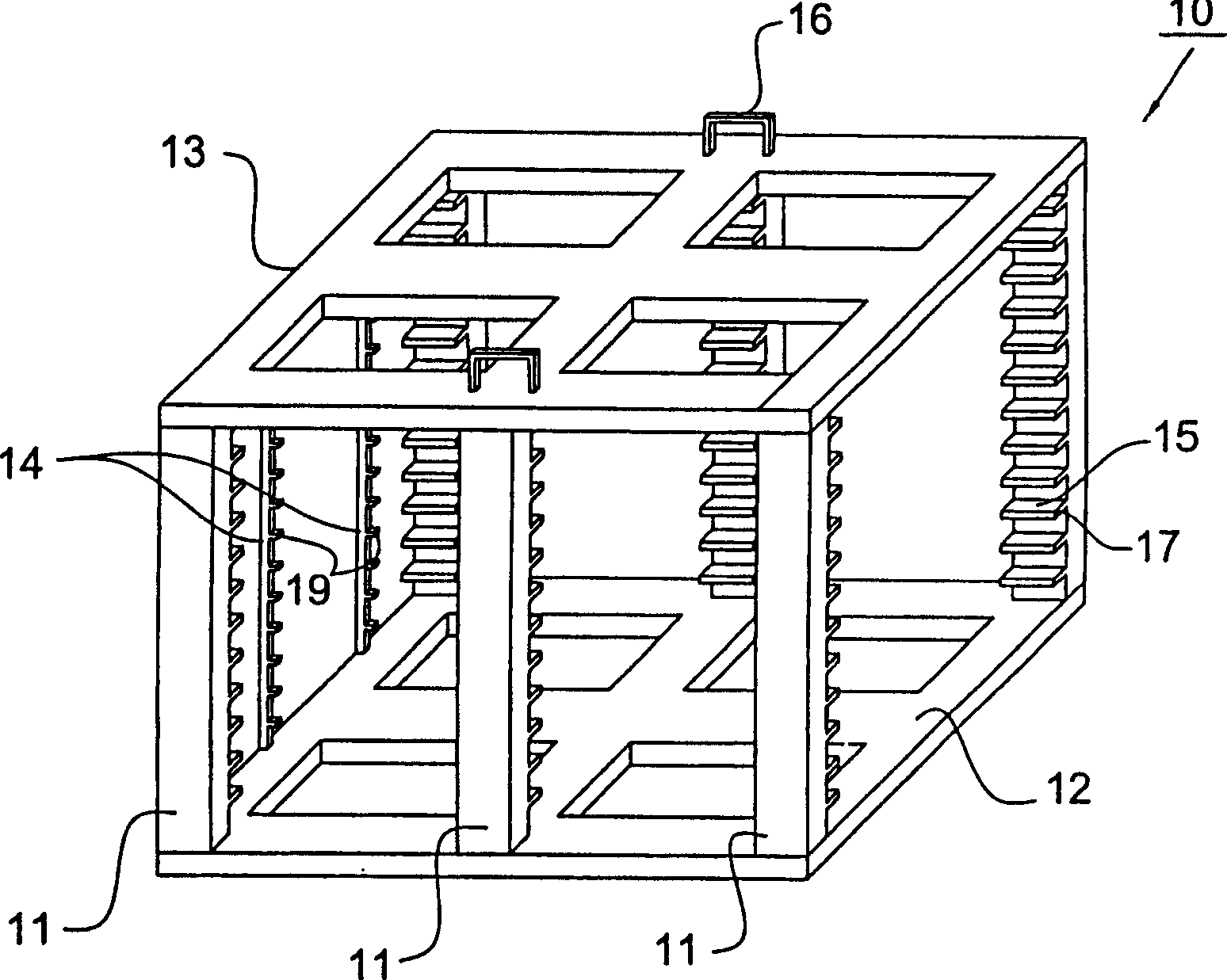
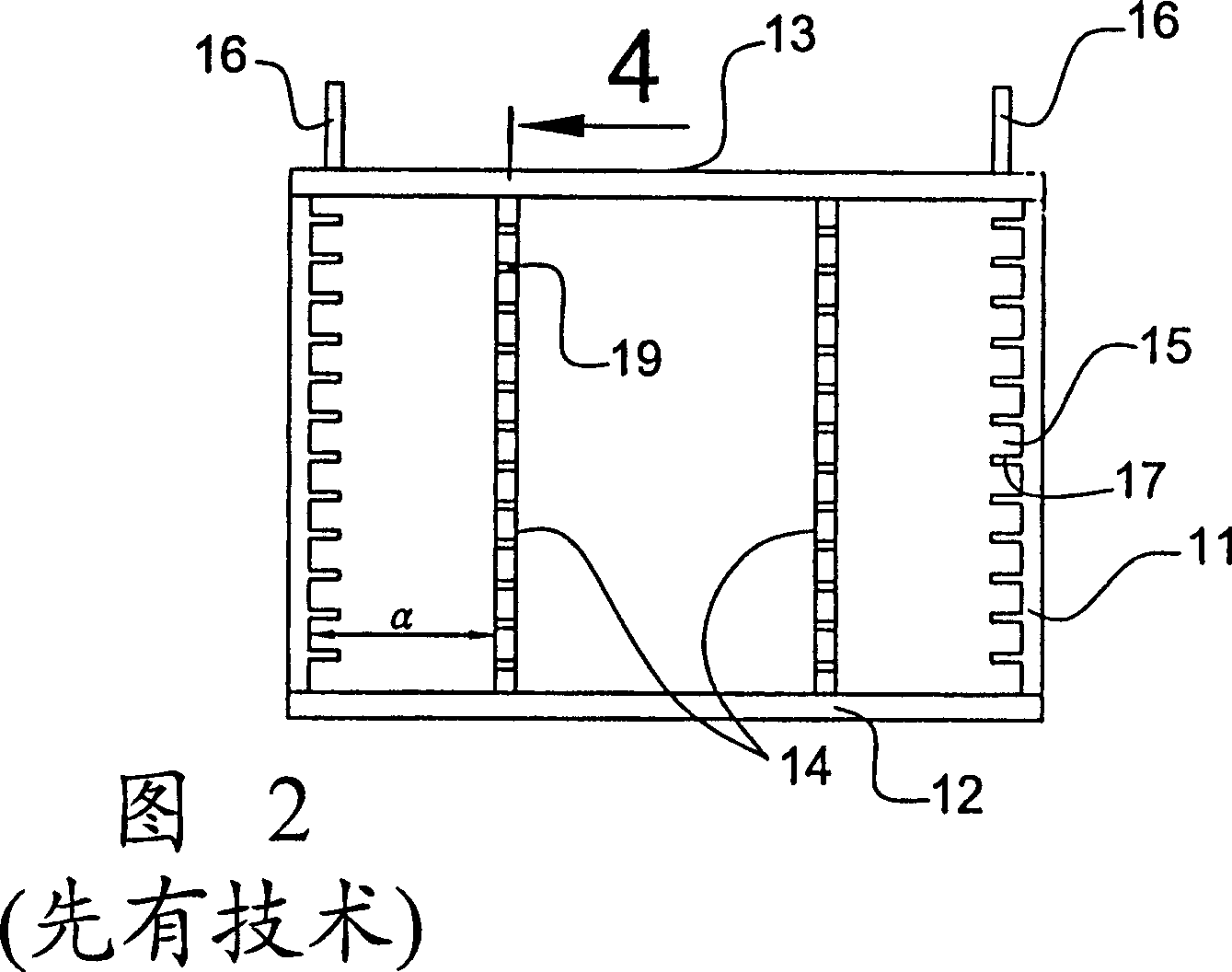
[0027] Referring now to FIG. 6, there is shown a liquid crystal display glass substrate cassette 50 in accordance with a first preferred embodiment of the present invention. The glass substrate box 50 includes a plurality of side plates 51 having a plurality of slots 55 formed by support members 57 for carrying the glass substrates, a bottom plate 52 and a top plate 53 . The substrate box 50 also includes two slidable end bars 54 and two handles 56, wherein the end bars 54 have stoppers 59, when the glass substrate is loaded in the substrate box 50, the end bars 54 The stopper 59 can be used to prevent the glass substrate from shifting, and the handle 56 can be used to carry the substrate box 50 conveniently.

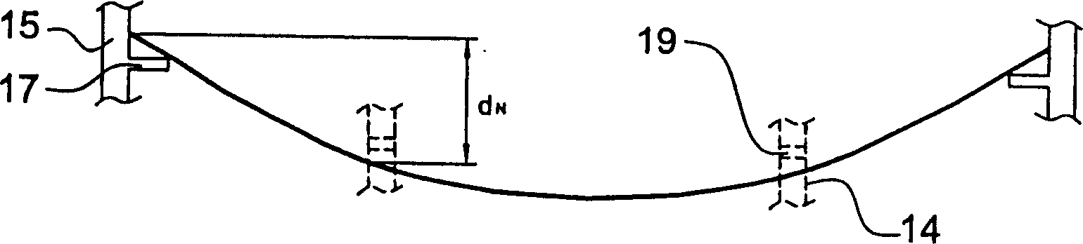
[0028] The feature of the present invention is that the end rod 54 can slide relative to the side plate 51 to adjust to match the natural drooping curve of the base plate to support the base plate. Preferably, the end rod 54 is placed between the groove 62 on one side ...


PUM


Abstract

The glass base plate box for liquid crystal display incldues one top board in the shape corresponding to the liquid crystal display and to define the two sides, one front end and one back end; the bottom board opposite to the top board; side boards between the top board and the bottom board, with several supports and forming several slots in certain intervals to bear several liquid crystal display base boards; and at least two ends rods extending between the top board and the bottom board and with several blocks for bearing the liquid crystal display base boards. The end rods may slide relatively to the side boards for regulating to match the natural suspending and bending and to support the base boards.

Description

technical field [0001] The invention relates to a glass substrate box for a liquid crystal display, in particular to a glass substrate box for a liquid crystal display, which can keep the distance between the glass substrates constant, so that a mechanical arm has a large operating margin when picking up the substrate. Background technique [0002] With the advancement of electronic technology, especially the prevalence of portable electronic products in daily life, there is an increasing demand for displays that are thin, light, small, and low-coupling. Liquid Crystal Display (LCD) is often used in such electronic products due to its advantages of low power consumption, low heat generation, light weight, and non-luminous display, and has even gradually replaced traditional Cathode ray tube monitor. [0003] A liquid crystal display device generally includes a pair of substrates, which are parallel to each other and separated by a gap. The gap between the two substrates is...

Claims


Application Information

Patent Timeline
IPC IPC(8): B65D85/00G02F1/1333
Inventor 陈猷仁潘泰吉
Owner INNOLUX CORP
Why Eureka
Try Eureka