
System and method for the detection and digitalization of the state of fresh concrete using infrared thermography and mathematical trend functions

An infrared thermal imaging, concrete technology, applied in the field of measurement or testing, can solve problems such as lack of meaning in detection

Pending Publication Date: 2021-04-09
数字化创新解决方案股份公司
View PDF2 Cites 2 Cited by
  • Summary
  • Abstract
  • Description
  • Claims
  • Application Information

AI Technical Summary

Problems solved by technology

[0008] On the other hand, in the method described in WO 2015 / 001344, all captured images correspond to concrete, so its detection lacks meaning

Method used


Image

  • System and method for the detection and digitalization of the state of fresh concrete using infrared thermography and mathematical trend functions
  • System and method for the detection and digitalization of the state of fresh concrete using infrared thermography and mathematical trend functions
  • System and method for the detection and digitalization of the state of fresh concrete using infrared thermography and mathematical trend functions

Examples


example 1

[0091] Example 1: Acquiring multiple thermal imaging images

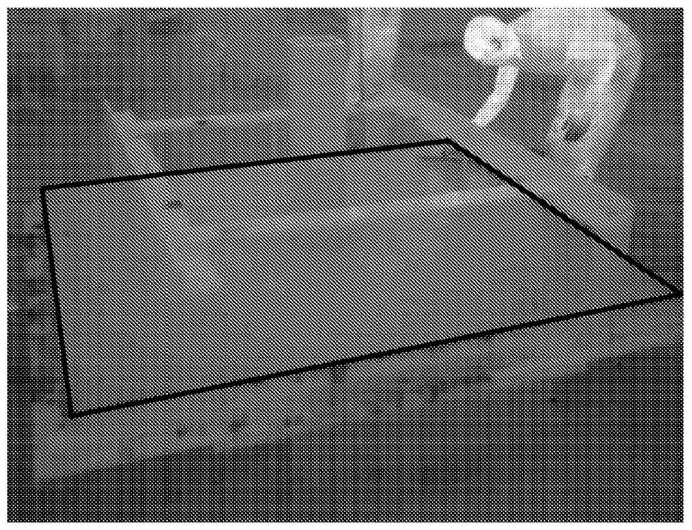
[0092] exist figure 1 In , an infrared thermography image captured during testing of the method of the present invention is shown. In this case, samples of fresh concrete were provided. The section containing fresh concrete has been delimited by means of black polygons which were not part of the original image but which have been incorporated for a better understanding of the invention. Additionally, on the freshly poured concrete section, the metal structure surrounding the concrete sample was seen, as well as the general background of the test.

[0093]Multiple infrared thermography images of the concrete samples were acquired at regular intervals of 15 minutes.

example 2

[0094] Example 2: Obtaining temperature curves and temperature profiles as a function of time

[0095] Figure 8 with Figure 9 Graphs showing temperature as a function of time correspond to pixels containing concrete and pixels not containing concrete, respectively.

[0096] In the graph, marker "A" corresponds to the temperature point measured from the thermographic image, "B" corresponds to the temperature curve as a function of time fitted to the temperature profile, and "C" corresponds to the temperature of the ambient temperature. Changes, and "D" correspond to changes in ambient temperature over the time frame of interest.

[0097] Additionally, in both figures the value ΔT A and ΔT CD , value ΔT A and ΔT CD correspond to the maximum ambient temperature difference and the difference between the maximum temperature and the initial temperature in the temperature profile as a function of time over the time range of interest, respectively.

[0098] exist Figure 8 w...

example 3

[0099] Example 3: Determine if a pixel corresponds to concrete

[0100] exist Figure 8 case, see the value ΔT corresponding to the indicated value CD Greater than the value ΔT A , in the example ΔT A has been used as a threshold. Therefore, from Figure 8 The pixels of the temperature profile will be identified as containing fresh concrete.

[0101] Instead, in Figure 9 case, see the value of ΔT CD less than the value ΔT A . Therefore, from Figure 9 The pixels of the temperature profile will be identified as pixels that do not contain fresh concrete.


PUM


Abstract

The invention relates to the use of thermal means for analysing materials, and specifically provides a system for detecting concrete using infrared thermography, comprising an information storage memory and a processor operatively connected to said memory, the processor being configured to save a plurality of infrared thermographic images to the memory; to obtain, for each pixel in the plurality of images, a temperature profile recorded as a function of time and a plurality of plots of temperature against time, each temperature plot being matched to a corresponding temperature profile recorded as a function of time; to determine an indicator value from each of the plots of temperature against time; and to specify that a pixel corresponds to concrete if the indicator value corresponding to the pixel is greater than a threshold value. The invention also relates to a method for detecting concrete using infrared thermography.

Description

technical field [0001] The present invention relates to the field of measurement or testing, in particular to the analysis of materials using thermal means, and in particular provides systems and methods for the detection of concrete by means of infrared thermography. Background technique [0002] In the construction sector, a recurring problem is monitoring the progress of construction work and the curing time of concrete. However, in order to monitor the progress of the construction work, first, the concrete on site needs to be inspected in order to provide further digitization. [0003] In the prior art it is known that the curing of concrete is an exothermic reaction. Once the concrete has been poured into the formwork, the grout begins an internal curing process which releases heat from within the mixture, causing an increase in temperature. Infrared thermography for studying structures containing concrete has been widely disclosed previously in the prior art. [000...

Claims


Application Information

Patent Timeline
Patent Type & Authority Applications(China)
IPC IPC(8): G01N25/72G01N33/38
CPCG01N25/72G01N33/383G06T7/001G06T2207/10016G06T2207/10048G06T2207/30132G01J2005/0077G01N25/4846G06T7/0004G06T2207/20024G01J5/485
Inventor 埃米利亚诺·安德烈斯·平托戈麦斯
Owner 数字化创新解决方案股份公司
Learn More