Railway vehicle and safety handrail thereof

A rail vehicle and safety technology, which is applied in the field of rail vehicles, can solve the problems that cannot meet the requirements of use, and the single-bar handrail cannot meet the requirements of use, so as to achieve the effects of improving passing efficiency, maximizing passing space, and reducing space

Active Publication Date: 2021-04-13
CRRC TANGSHAN CO LTD
View PDF8 Cites 2 Cited by
  • Summary
  • Abstract
  • Description
  • Claims
  • Application Information

AI Technical Summary

Problems solved by technology

However, when the width of the passing door exceeds the installation height of the safety handrail from the floor surface, the safety handrail will interfere with the floor surface when retracted, resulting in failure to meet the use requirements
[0004] To sum up, the existing sa

Method used


Image

  • Railway vehicle and safety handrail thereof
  • Railway vehicle and safety handrail thereof
  • Railway vehicle and safety handrail thereof

Examples


Embodiment 1

[0058] The embodiment of the present application provides a safety handrail 4 for rail vehicles, such as Figure 6 and Figure 7 As shown in the structure, the safety handrail 4 includes an outer tube 41 and an inner tube 42; wherein:

[0059] The inner tube 42 has a first end and a second end oppositely arranged, the first end is slidably installed in the outer tube 41, and the second end is provided with a locking hole 4251;

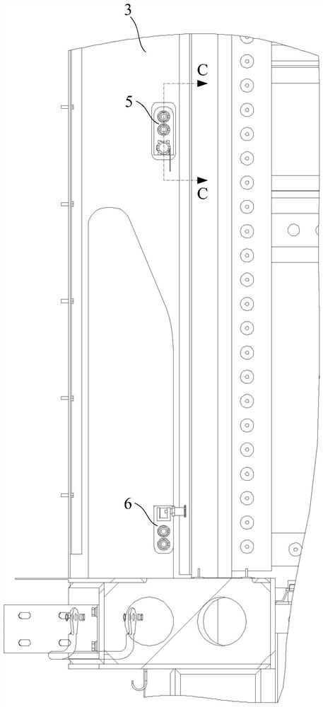
[0060] Such as Figure 8 As shown in the structure, the outer tube 41 is fixedly connected with a limit sleeve 411 on the end face facing the inner tube 42, and a hinged joint 412 is detachably installed at the end away from the inner tube 42. The limit sleeve 411 is used to connect the first end of the inner tube 42 One end is limited in the outer tube 41;

[0061] The outer peripheral surface of the outer tube 41 is covered with a warning sign 43 that can rotate around the axis of the outer tube 41 .

[0062] Because one end of the inner tube 42 ...

Embodiment 2

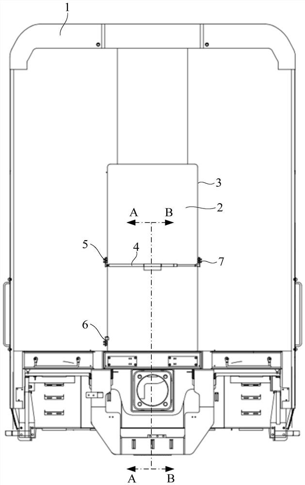
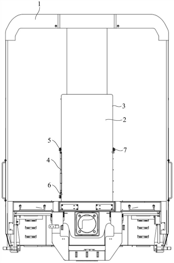
[0077] The embodiment of the present application also provides a rail vehicle, such as figure 1 and figure 2 As shown in the structure, the rail vehicle includes a car body 1. The car body 1 is provided with a door column 3 forming a passage door 2, and also includes a mounting seat fixed on the door column 3 and any safety handrail provided by the above-mentioned embodiments. 4; The schematic diagram of the use status of the safety handrail 4 during work can be referred to figure 1 , and the structural schematic diagram when the safety handrail 4 is in retracted state can refer to figure 2 The mounting base includes an outer tube mounting base 5, a first inner tube mounting base 6 and a second inner tube mounting base 7 coplanarly arranged, wherein the outer tube mounting base 5 is vertically opposite to the first inner tube mounting base 6 Setting, the outer tube mounting seat 5 and the second inner tube mounting seat 7 are relatively arranged along the horizontal direct...


PUM


Abstract

The embodiment of the invention relates to the technical field of railway vehicles, and concretely relates to a railway vehicle and a safety handrail thereof. The safety handrail comprises an outer pipe and an inner pipe. Wherein the inner pipe is provided with a first end and a second end which are oppositely arranged, the first end can be installed in the outer pipe in a sliding mode, and the second end is provided with a locking hole; a limiting sleeve is fixedly connected to the end face, facing the inner pipe, of the outer pipe, a hinge joint is detachably installed at the end, away from the inner pipe, of the outer pipe, and the limiting sleeve is used for limiting the first end of the inner pipe into the outer pipe; and the outer circumferential face of the outer pipe is sleeved with a warning sign capable of rotating around the axis of the outer pipe. The safety handrail has the advantages of being adjustable in length and small in occupied space in the width direction of the passing door during retracting, the situation that the designed width of the passing door is large can be met, and the passing efficiency of the passing door can be improved.

Description

technical field [0001] The present application relates to the technical field of rail vehicles, in particular, to a rail vehicle and a safety handrail thereof. Background technique [0002] Existing rail cars generally install safety handrails at the passing doors at the end of the car; when the safety handrails are placed horizontally at the door, passengers can be intercepted and warned by the safety handrails; and when passengers and staff need to pass, the safety handrails can be rotated to the vertical position. The existing safety handrails at the end of the car all adopt a single-rod structure, and the mounting seat at the end of the fixed safety handrail is fixed on the passing door column through two fixed points, the upper and the lower. [0003] The width design of the door at the end of the car needs to meet the requirements for passengers to pass through, and it is generally greater than 28 inches, that is, 711.2mm. The height of the safety handrail is require...

Claims


Application Information

Patent Timeline
IPC IPC(8): B61D37/00B60N3/02
CPCB61D37/00B60N3/02B60N3/026
Inventor 杨红娜李朝万红雨周强王茂权于文学安超林琳庹霞张爱华
Owner CRRC TANGSHAN CO LTD
Why Eureka
Try Eureka