A rail vehicle and its safety handrail

A technology for rail vehicles and handrails, which is applied in the field of rail vehicles, can solve the problems that single-bar handrails cannot meet the use requirements and can not meet the use requirements, etc., and achieves the effects of improving the passing efficiency, reducing the space, and adjusting the length.

Active Publication Date: 2022-07-26
CRRC TANGSHAN CO LTD
View PDF8 Cites 0 Cited by
  • Summary
  • Abstract
  • Description
  • Claims
  • Application Information

AI Technical Summary

Problems solved by technology

However, when the width of the passing door exceeds the installation height of the safety handrail from the floor surface, the safety handrail will interfere with the floor surface when retracted, resulting in failure to meet the use requirements
[0004] To sum up, the existing safety handrail with single-pole structure is only suitable for the case where the width of the passing door is smaller than the installation height of the handrail rod. When the design width of the passing door is large, the single-pole handrail cannot meet the requirements of use

Method used


Image

  • A rail vehicle and its safety handrail
  • A rail vehicle and its safety handrail
  • A rail vehicle and its safety handrail

Examples


Embodiment 1

[0058] The embodiment of the present application provides a safety handrail 4 for rail vehicles, such as Image 6 and Figure 7 As shown in the structure, the safety handrail 4 includes an outer tube 41 and an inner tube 42; wherein:

[0059] The inner tube 42 has a first end and a second end oppositely arranged, the first end can be slidably installed in the outer tube 41, and the second end is provided with a locking hole 4251;

[0060] like Figure 8 As shown in the structure, the outer tube 41 is fixedly connected with a limiting sleeve 411 at the end face facing the inner tube 42, and a hinged joint 412 is detachably installed at the end away from the inner tube 42. The limiting sleeve 411 is used to connect the first One end is limited to the outer tube 41;

[0061] The outer peripheral surface of the outer tube 41 is sleeved with a warning sign 43 that can rotate around the axis of the outer tube 41 .

[0062] Since one end of the inner tube 42 of the above-mentione...

Embodiment 2

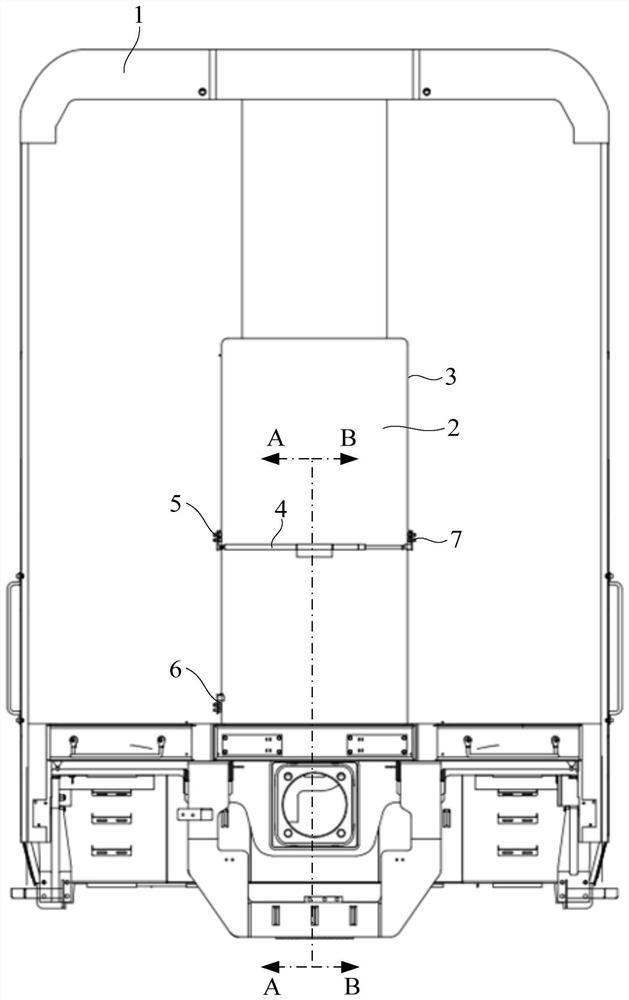
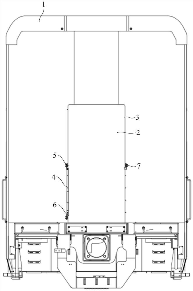
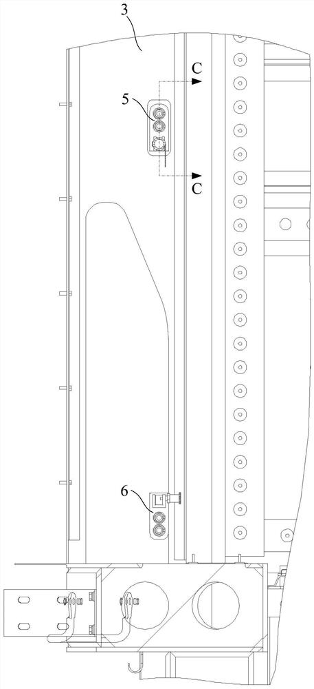
[0077] The embodiments of the present application also provide a rail vehicle, such as figure 1 and figure 2 As shown in the structure, the rail vehicle includes a vehicle body 1, which is provided with a door pillar 3 formed through the door 2, a mounting seat fixedly mounted on the door pillar 3, and any one of the safety handrails provided in the above embodiments. 4; The schematic diagram of the use state of the safety handrail 4 during the working process can be referred to figure 1 , and the schematic diagram of the structure when the safety handrail 4 is in the retracted state can refer to figure 2 ; The mounting seat includes a coplanar outer tube mounting seat 5, a first inner tube mounting seat 6 and a second inner tube mounting seat 7, wherein the outer tube mounting seat 5 and the first inner tube mounting seat 6 are opposite in the vertical direction Set, the outer tube mounting seat 5 and the second inner tube mounting seat 7 are arranged opposite to each oth...


PUM


Abstract

The embodiments of the present application relate to the technical field of rail vehicles, and in particular, to a rail vehicle and a safety handrail thereof. The safety handrail includes an outer tube and an inner tube; the inner tube has a first end and a second end arranged oppositely, the first end can be slidably installed in the outer tube, and the second end is provided with a locking hole; the outer tube The pipe is fixedly connected with a limiting sleeve on the end face facing the inner pipe, and a hinge joint is detachably installed at one end away from the inner pipe, and the limiting sleeve is used to limit the first end of the inner pipe to It is located in the outer tube; the outer peripheral surface of the outer tube is sleeved with a warning sign that can rotate around the axis of the outer tube. The safety handrail of the present application has the characteristics of adjustable length and less space in the width direction of the passing door when retracted, which can meet the design width of the passing door and improve the passing efficiency of the passing door.

Description

technical field [0001] The present application relates to the technical field of rail vehicles, in particular, to a rail vehicle and a safety handrail thereof. Background technique [0002] Safety handrails are generally installed at the passing doors of existing rail cars; when the safety handrails are placed horizontally at the door, passengers can be intercepted and warned by the safety handrails; and when passengers and staff need to pass through, the safety handrails can be rotated. to the vertical state. The safety armrests at the existing vehicle end all adopt a single-rod structure, and the mounting seat for fixing the end of the safety armrest is fixed on the passing door column through two upper and lower fixing points. [0003] The width design of the vehicle-end passing door needs to meet the requirements of passengers passing through, which is generally greater than 28 inches, or 711.2 mm. The height of the safety handrail can be used by the disabled, and it i...

Claims


Application Information

Patent Timeline
Patent Type & Authority Patents(China)
IPC IPC(8): B61D37/00B60N3/02
CPCB61D37/00B60N3/02B60N3/026
Inventor 杨红娜李朝万红雨周强王茂权于文学安超林琳庹霞张爱华
Owner CRRC TANGSHAN CO LTD
Why Eureka
Try Eureka