
Adjustable rod stopper

An adjustable, one-to-one technology, applied in the field of fishing gear, can solve problems such as use restrictions, and achieve the effect of firm locking and flexible fixed positions

Inactive Publication Date: 2021-04-16
刘华军
View PDF0 Cites 0 Cited by
  • Summary
  • Abstract
  • Description
  • Claims
  • Application Information

AI Technical Summary

Problems solved by technology

Existing rod stops must precisely match the outer diameter of the fishing rod, limiting use

Method used


Image

  • Adjustable rod stopper
  • Adjustable rod stopper
  • Adjustable rod stopper

Examples


Embodiment approach

[0054] Such as Figure 18 with Figure 19 As shown, it is the second embodiment of the adjustable rod stop of the present invention. The difference from the first embodiment is that the side wall of the center cylinder 21A of the center head 2A is provided with a through center card Port 200A. The rotating ring 51A is provided with a rotating ring bayonet 515A in the radial direction, and the fixed ring 52A is provided with a fixed ring bayonet 525A in the radial direction. The rotating body 31A of the rotating head 3A is provided with a rotating head bayonet 325A in the radial direction.

[0055] When in use, the user can use the center bayonet 200A to directly snap the center head 2A onto the fishing rod 6 from the outside without penetrating through the head of the fishing rod 6 to avoid changing rods midway. Install the same way, snap the two swivel heads 3A onto the fishing rod 6 . Finally, just lock the two rotating heads 3A.


PUM


Abstract

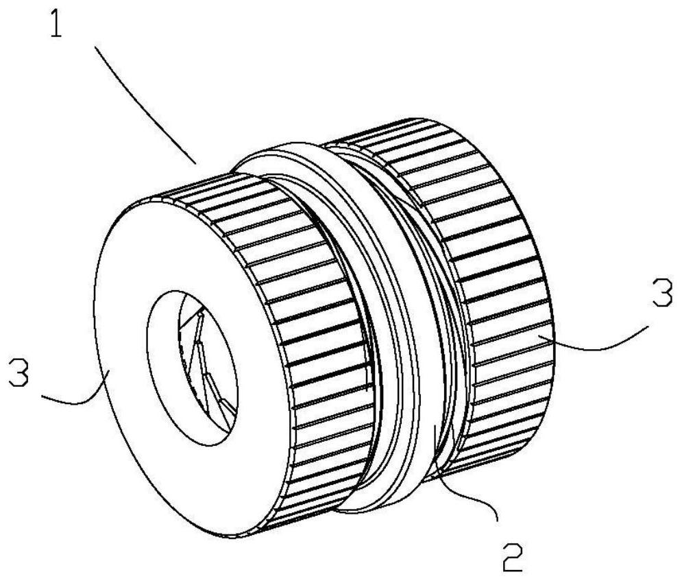
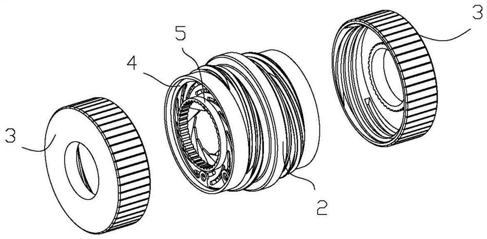
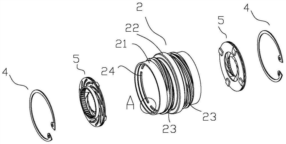
The invention discloses an adjustable rod stopper. The adjustable rod stopper comprises a middle head, a pair of locking assemblies and a pair of rotating heads; The pair of the locking assemblies are detachably arranged at two ends of the middle head; and the pair of the rotating heads are detachably arranged at two ends of the middle head. When the rotating heads are screwed tightly, the locking assemblies tightly hold a fishing rod. Due to an adoption of a double-head locking structure, the locking is firm, a fixing position is flexible, and the adjustable rod stopper is particularly suitable for Taiwan fishing.

Description

technical field [0001] The invention relates to a fishing tool, more precisely, an adjustable rod stop. Background technique [0002] Taiwan fishing, also known as table fishing, is a popular fishing method in recent years. When fishing in Taiwan, it is necessary to slightly press the rod of the fishing rod into the water, therefore, it is necessary to set a rod stop on the fishing rod to prevent the fishing rod from slipping into the water. Existing rod stoppers must precisely match the outer diameter of the fishing rod, and their use is limited. Contents of the invention [0003] The present invention mainly solves the technical problems existing in the prior art, thereby providing an adjustable rod stop. [0004] Above-mentioned technical problem of the present invention is mainly solved by following technical scheme: [0005] An adjustable rod stop, characterized in that the adjustable rod stop includes: [0006] a central head; [0007] A pair of locking componen...

Claims


Application Information

Patent Timeline
IPC IPC(8): A01K87/00
Inventor 不公告发明人
Owner 刘华军
Learn More