
A fire-proof and flame-retardant system for self-checking the temperature of building fresh air exhaust ducts

An exhaust duct, fire and flame retardant technology, which is applied in the field of green building safety, can solve the problems of ventilation and emission of smoke by-products that cannot be caused by fire, aggravated fire situation, and isolation of fire sources.

Active Publication Date: 2022-01-07
拉米尼特建筑系统(苏州)有限公司
View PDF4 Cites 0 Cited by
  • Summary
  • Abstract
  • Description
  • Claims
  • Application Information

AI Technical Summary

Problems solved by technology

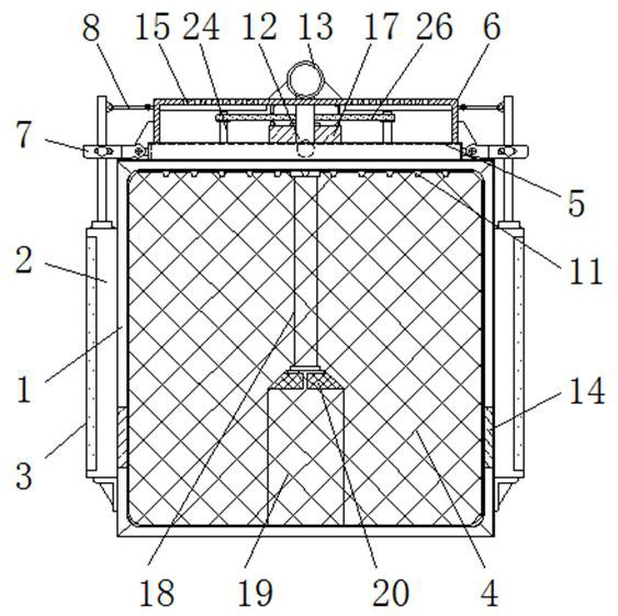
[0007] The purpose of the present invention is to provide a building fresh air exhaust pipe temperature self-checking barrier fire prevention and flame retardant system to solve the above background technology. It is proposed that the existing building fresh air pipe laying and installation can only carry out conventional ventilation settings, in case of fire etc. When the fire occurs, it is not possible to block and block the pipeline, which will cause the spread of the fire and aggravate the fire situation. When the fire occurs, timely and accurate fire source blocking cannot be carried out. When the fire source is blocked and isolated, it is impossible to Conventional ventilation and discharge of dense smoke by-products of the fire source will easily lead to a large amount of dense smoke gathering indoors at the fire source site, affecting the visibility of the indoor environment of the building, and causing subsequent fire fighting and rescue problems at the fire source site

Method used


Image

  • A fire-proof and flame-retardant system for self-checking the temperature of building fresh air exhaust ducts
  • A fire-proof and flame-retardant system for self-checking the temperature of building fresh air exhaust ducts
  • A fire-proof and flame-retardant system for self-checking the temperature of building fresh air exhaust ducts

Examples


Embodiment Construction

[0028] The following will clearly and completely describe the technical solutions in the embodiments of the present invention with reference to the accompanying drawings in the embodiments of the present invention. Obviously, the described embodiments are only some, not all, embodiments of the present invention. Based on the embodiments of the present invention, all other embodiments obtained by persons of ordinary skill in the art without making creative efforts belong to the protection scope of the present invention.

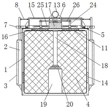
[0029] see Figure 1-7 , the present invention provides a technical solution: a building fresh air exhaust pipe temperature self-checking barrier fire retardant system, including pipe body 1, telescopic rod 2, kerosene liquid 3, isolation net 4, liquid outlet pipe 5, sealing chamber 6 , connecting piece 7, connecting rod 8, horizontal shaft 9, magnet block 10, liquid outlet head 11, conduit 12, external water pipe 13, heat conducting sheet 14, vent hole 15, me...


PUM


Abstract

The invention discloses a building fresh air exhaust pipe temperature self-inspection barrier fire prevention and flame retardant system, which includes a pipe body, a conduit, a vent hole, a rotating shaft and side guide rails, and telescopic rods are fixedly installed on the outer walls of the left and right sides of the pipe body , and the interior of the telescopic rod is provided with kerosene liquid, and the inner wall of the pipeline body is fixedly installed with an isolation net, and the middle and end of the outer wall of the output shaft of the telescopic rod are respectively rotatably installed with a connecting piece and a connecting rod, and the end of the connecting piece One end of the horizontal shaft is hinged on the upper part, and the bottom of the liquid outlet pipe is provided with a liquid outlet head, and the liquid outlet head is located inside the pipe body. The building's fresh air exhaust duct temperature self-inspection barrier fire and flame retardant system is distributed in the interior of the duct at intervals, which can cool down the fire source and extinguish the fire with oxygen isolation under the action of the temperature change of the fire source, and will not cause loss of fire during fire extinguishing The smoke is collected for continuous and uninterrupted emission of smoke.

Description

technical field [0001] The invention relates to the technical field related to green building safety, in particular to a temperature self-checking and blocking fire-proof and flame-retardant system of a building fresh air exhaust duct. Background technique [0002] The building fresh air duct is installed in a large space building facility to carry out air guidance and exhaust facilities for the indoor and outdoor environment of the building. The regulation and circulation of the building enable people living in the room to breathe clean and fresh air in their long-term life, and the laying and setting of fresh air ducts can stably discharge and subsequently effectively purify the dirty gas in the building. [0003] However, the existing building fresh air ducts have the following problems in use: [0004] 1. The laying and installation of pipelines can only be done with conventional ventilation settings. When a fire occurs, the pipeline cannot be blocked and blocked, which...

Claims


Application Information

Patent Timeline
Patent Type & Authority Patents(China)
IPC IPC(8): A62C3/00A62C2/04A62C2/06A62C5/00A62C37/42A62C99/00F24F7/06F24F11/33
Inventor 杨苏琴
Owner 拉米尼特建筑系统(苏州)有限公司
Learn More