Continuous fixed quantity discharging device and material blending system using the same

A technology of discharge device and discharge port, which is applied in the direction of measuring device, feeding device, weighing equipment for automatic feeding/discharging, etc., can solve the problems of reducing discharge amount, unable to discharge materials smoothly and continuously, and easy deviation of materials.

Inactive Publication Date: 2007-06-06
MATSUI MFG
View PDF1 Cites 10 Cited by
  • Summary
  • Abstract
  • Description
  • Claims
  • Application Information

AI Technical Summary

Problems solved by technology

[0007] However, in this continuous quantitative discharge device, two material storage containers are required, and a metering unit needs to be provided in each of these two material storage containers, so there is a problem of increasing the size due to the complicated structure.
[0008] In addition, since the continuous quantitative discharge device is a structure in which the two material storage containers are synchronized with the quantitative discharge device, there is a problem that, when a large amount of material is continuously discharged, etc., the material storage container will not Waiting until the material can be discharged quantitatively, or in order to discharge the material quantitatively in any material storage container, it is necessary to perform adjustments such as reducing the discharge amount or reducing the discharge speed, and the material cannot be discharged smoothly and continuously

Method used


Image

  • Continuous fixed quantity discharging device and material blending system using the same
  • Continuous fixed quantity discharging device and material blending system using the same
  • Continuous fixed quantity discharging device and material blending system using the same

Examples


Embodiment 1

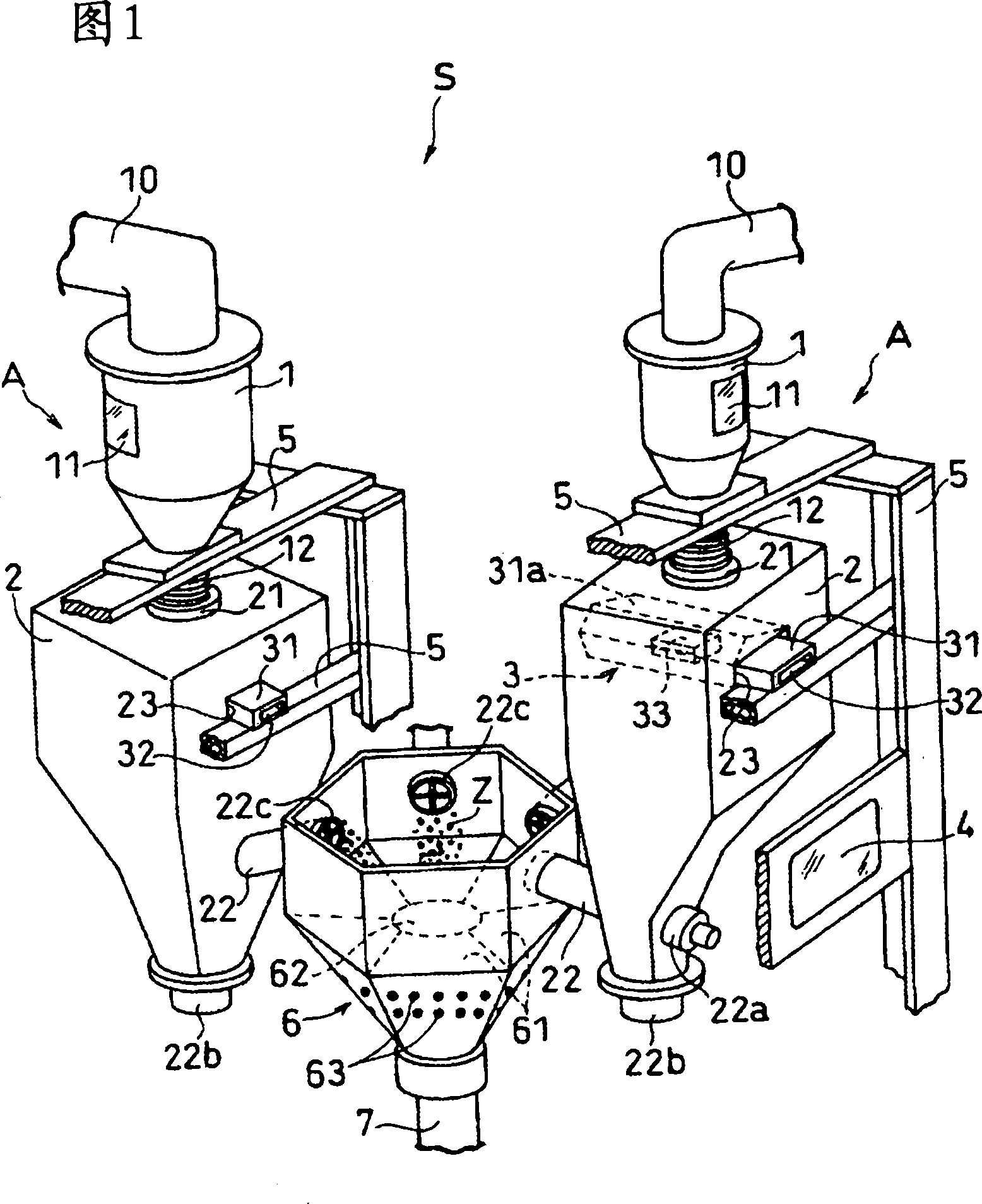
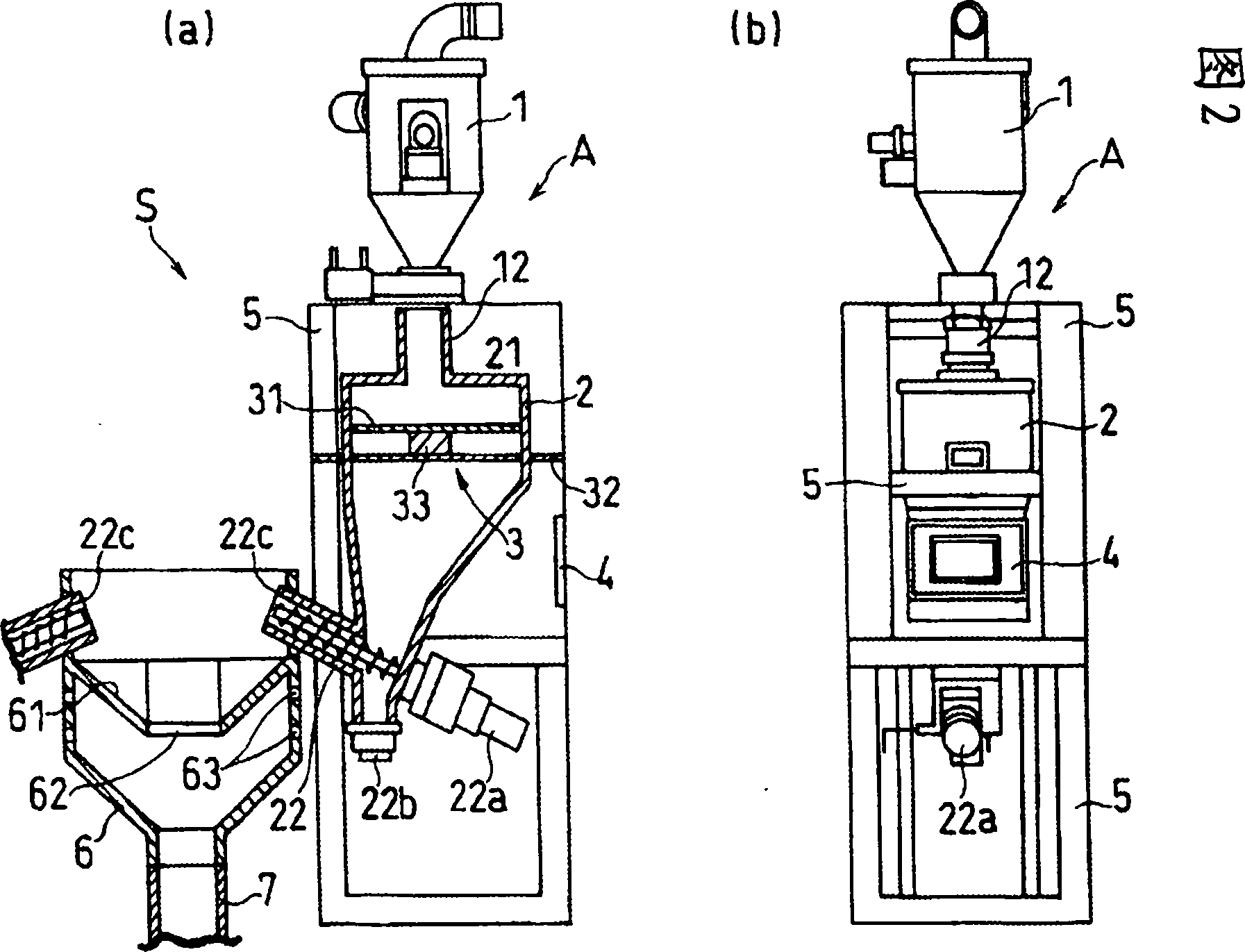
[0081] FIG. 1 is a schematic overall perspective view showing a partially cutaway state of one embodiment of a material blending system S using a continuous quantitative discharge apparatus A according to the present invention. FIG. 2 is an explanatory view schematically showing a part of FIG. (a) is a schematic vertical cross-sectional view of a partly cutaway state of FIG. 1, and FIG. 2 (b) is a schematic front view of the state of the continuous quantitative discharge device A of FIG. 1 seen from the control unit.

[0082] First, the continuous quantitative discharge device A according to the present invention will be described.

[0083] The continuous quantitative discharge device A is composed of a material retention tank 1, a material storage container 2, a load cell type mass measuring unit 3, a control unit 4 and an outer frame frame 5,

[0084] The material retention tank 1 is used to retain the material Z continuously supplied by the supply member 10;

[0085] The m...


PUM


Abstract

To provide a continuous fixed quantity discharging device and a material blending system using the device reduced in overall size and capable of accurately, smoothly, and continuously discharging a fixed quantity of material and mixing the discharged material at a uniform mixing ratio. This continuous fixed quantity discharging device comprises a material reserving tank (1) for reserving the material (Z) continuously fed by a supply means (10), a material storage tank (2) having a material inlet (21) separated from the material reserving tank (1) formed at the upper part, storing the material (Z) fallen from the material reserving tank (1), and having a discharge device (22) capable of continuously discharging the fixed quantity of the reserved material (Z) formed at the lower part, a load cell type mass weighing part (3) formed by installing a carrying arm (31) connected to only the material storage tank (2) in the material storage tank (2) and supporting the carrying arm (31) by a load cell (33) installed on a support frame (32) separated from the material storage tank (2) in a non-contact state, and a control part (4) monitoring the values weighed by the load cell (33) and controlling the discharge of the material by the discharge device (22) and/or the supply of the material into the storage tank (2) by the discharge device.

Description

technical field [0001] The present invention relates to a continuous quantitative discharge device of a weight loss compensation method and a material blending system using the same. The above-mentioned stored material is discharged, and the material whose mass has decreased is regarded as the discharged material, and a certain amount of material can be continuously discharged. Background technique [0002] As a means of continuously discharging a certain amount of material, a weight loss compensation method is known. [0003] As a conventional continuous quantitative discharge device based on this weight loss compensation method, it is composed of a metering device, a supply device, and a control device. The material storage container, and the metering part composed of a quantitative discharge device arranged at the lower part of the material storage container; the supply device can supply to both of the above-mentioned metering parts arranged in parallel; the control devi...

Claims


Application Information

Patent Timeline
IPC IPC(8): G01G13/16B01F15/02B01F15/04B01J4/00B65G65/40G01G19/32
CPCG01G13/16B01F5/246G01G13/248B01F15/0445G01G23/3735B01F25/83B01F35/881
Inventor 花冈一成奥田隆行原洋
Owner MATSUI MFG
Why Eureka
Try Eureka