High-pressure tank having structure for radiation of heat and discharge of remaining gas and method of manufacturing the same

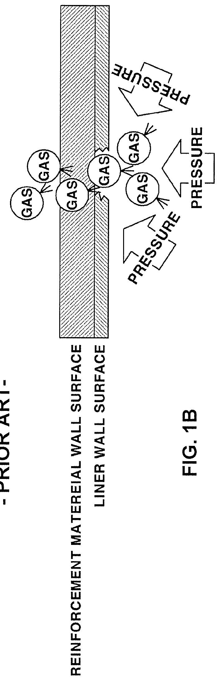
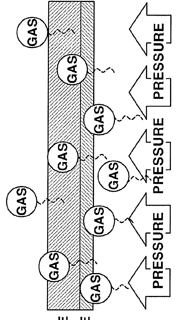
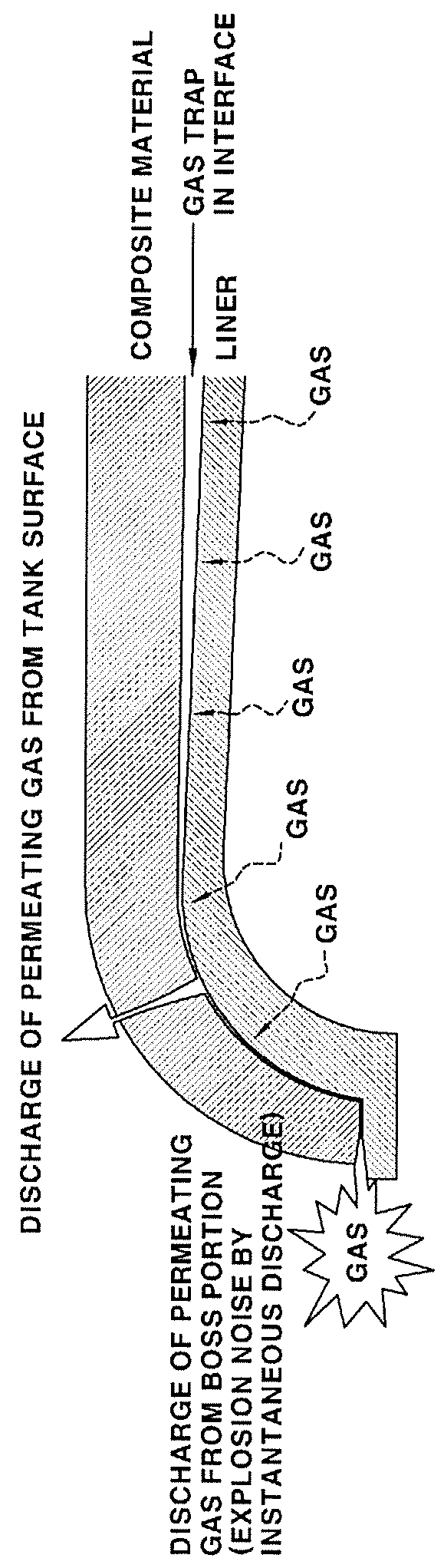
a high-pressure tank and structure technology, which is applied in the manufacture of final products, propulsion parts, climate sustainability, etc., can solve the problems of reducing the inner volume of the high-pressure tank, reducing the efficiency of weight reduction, and limiting the extent to which the inner volume of the tank may be increased, so as to prevent the instantaneous discharge of an excessive amount of gas and prevent the occurrence of buckling (damage) of the liner. , the effect of preventing

Inactive Publication Date: 2018-09-27
HYUNDAI MOTOR CO LTD +2
View PDF5 Cites 11 Cited by
  • Summary
  • Abstract
  • Description
  • Claims
  • Application Information

AI Technical Summary

Benefits of technology

[0079]According to the present disclosure, gas that has permeated a liner may be continuously discharged outward, rather than remaining in the interface between the liner and a composite material. Accordingly, an unpredictable situation in which an excessive amount of gas remaining in the interface between the liner and the composite material is discharged all at once may be prevented.
[0080]In addition, according to the present disclosure, it is possible to prevent the instantaneous discharge of an excessive amount of remaining gas from being mistakenly presumed to be gas leakage, or to prevent damage to the liner due to gas that is not discharged outward.
[0081]In addition, according to the present disclosure, in the state in which the high-pressure tank is at a low pressure, it is possible to prevent the occurrence of buckling (damage) of the liner caused when the gas that has permeated the liner and remains between the liner and the composite material applies pressure to the liner.
[0082]In addition, according to the present disclosure, since a heat-transfer sheet may be formed along the outer circumferential surface of the liner, heat that may be generated inside the liner due to adiabatic compression when the high-pressure tank is charged with high-pressure gas may be uniformly and rapidly distributed to the entire high-pressure tank, which may suppress an increase in the temperature of the high-pressure tank.

Problems solved by technology

Considering the high-pressure tank of the above-described configuration in detail, the high-pressure tank is difficult to form in a size exceeding a given volume in order to be mounted in the fuel cell system, and thus there is a limit to the extent to which the inner volume of the tank may be increased.
To this end, although there is a method of increasing the thickness of the wall, i.e. the cross section of the high-pressure tank, this method may cause deterioration in weight efficiency and a reduction in the inner volume of the high-pressure tank.
The type-3 liner has higher gas safety than the type-4 liner, but is expensive and has poor fatigue resistance, whereas the type-4 liner is cheaper than the type-3 liner and has good fatigue-resistance, but exhibits poor gas anti-permeation performance.
In the type-4 liner described above, referring to FIGS. 1A, 1B and 2, in the state in which high-pressure gas is stored inside the liner, the gas may permeate the polymer liner to thereby be discharged to the outer surface of a high-pressure tank, which may lead to the mistaken perception that gas is leaking from the high-pressure tank.
In addition, referring to FIG. 3, when the pressure inside the liner is lower than the pressure in the interface between the liner and a composite material, permeating gas (remaining gas), which has remained in the interface between the liner and the composite material, may cause inward buckling of the liner, thus causing deformation of the liner.

Method used


Image

  • High-pressure tank having structure for radiation of heat and discharge of remaining gas and method of manufacturing the same
  • High-pressure tank having structure for radiation of heat and discharge of remaining gas and method of manufacturing the same
  • High-pressure tank having structure for radiation of heat and discharge of remaining gas and method of manufacturing the same

Examples


Embodiment Construction

[0042]Hereinafter, the exemplary embodiments of the present disclosure will be described in detail with reference to the accompanying drawings. The exemplary embodiments of the present disclosure may be modified in many different forms, and the scope of the present disclosure should not be construed as being limited to the following embodiments. These exemplary embodiments are provided so that this disclosure will be through and complete and will fully convey the scope to those skilled in the art.

[0043]In addition, for example, suffixes “portion”, “unit”, and “module” used herein mean an element that processes at least one function or operation, and may be realized by hardware or software, or by a combination of hardware and software.

[0044]A fuel cell system mounted in a vehicle may generally include, for example, a fuel cell stack for generating electricity, a fuel supply device for supplying fuel gas (hydrogen) to the fuel cell stack, an air supply device for supplying oxygen in a...


PUM

PropertyMeasurementUnit
pressureaaaaaaaaaa
pressureaaaaaaaaaa
thicknessaaaaaaaaaa

Abstract

A high-pressure includes a liner; a composite material surrounding an outer circumferential surface of the liner; a heat-transfer sheet formed on the outer circumferential surface of the liner; and a spacer disposed between the heat-transfer sheet and the composite material. The heat-transfer sheet and the spacer have a gap therebetween.

Description

CROSS-REFERENCE TO RELATED APPLICATION[0001]This application claims under 35 U.S.C. § 119(a) the benefit of priority to Korean Patent Application No. 10-2017-0037660 filed on Mar. 24, 2017, the entire content of which is incorporated herein by reference.TECHNICAL FIELD[0002]The present disclosure relates to a structure of a high-pressure tank, which stores high-pressure fuel in a fuel cell system, capable of outwardly discharging gas and of dissipating heat generated when the high-pressure fuel is charged.BACKGROUND[0003]Generally, a fuel cell system includes a fuel cell stack for generating electricity, a fuel supply system for supplying fuel (hydrogen) to the fuel cell stack, an air supply system for supplying oxygen in air, which is an oxidant required for electrochemical reaction, to the fuel cell stack, and a heat and water management system for controlling the operating temperature of the fuel cell stack. The fuel supply system, i.e. a hydrogen supply system includes a high-pr...

Claims


Application Information

Patent Timeline
Patent Type & Authority Applications(United States)
IPC IPC(8): F17C1/16B29C70/70
CPCF17C1/16B29C70/70B29C70/32B29K2307/04B29K2063/00B29K2623/06B29K2677/00B29L2031/7126F17C2203/0604F17C2203/0609F17C2203/0621F17C2203/0636F17C2203/066F17C2203/0687F17C2205/0153F17C2209/227F17C2209/2154F17C2270/0184F17C2201/0109B60K15/03006B60K2015/03032B60K2015/03315H01M8/04089F17C1/00F17C1/06F17C13/00F17C13/002H01M8/04F17C2209/22F17C2221/012B60K15/03177B60K2015/03046B29C53/56H01M8/04201H01M2250/20F17C2203/068F17C2201/056F17C2203/0619F17C2203/0624F17C2203/0646F17C2203/0648F17C2203/0663F17C2205/0305F17C2221/011F17C2221/031F17C2223/0123F17C2223/036F17C2260/037F17C2270/01Y02E60/32Y02P70/50Y02T90/40Y02E60/50F17C13/12F17C2203/012F17C2209/232
Inventor CHUNG, JAE HANKIM, JONG LYULYOO, GYE HYOUNGHEO, SEOK BONG
Owner HYUNDAI MOTOR CO LTD
Why Eureka
Try Eureka