
Image splicing method, computer readable storage medium and computer equipment

An image stitching and image technology, applied in the field of image processing, can solve problems such as misalignment of panoramic cameras, large parallax between lenses, and inability to obtain top/bottom images, etc., to solve alignment errors, simplify the calculation process, avoid complex calculations and The effect of the risk of error

Active Publication Date: 2021-04-16
SHENZHEN ARASHI VISION CO LTD
View PDF8 Cites 1 Cited by
  • Summary
  • Abstract
  • Description
  • Claims
  • Application Information

AI Technical Summary

Problems solved by technology

However, for the most common panoramic camera structure in which multiple lenses are arranged in a ring, the bottom and top of the panoramic sphere are spliced ​​together by all the lens images. In the perspective of the viewer of the panoramic image, the top area and the bottom area of ​​the panoramic sphere are respectively composed of Multiple fan-shaped pictures are stitched together, and all the stitching seams are gathered at the center; due to the parallax between the lenses, the misalignment between the pictures is serious, so that the top and bottom of the panoramic camera will have alignment errors, picture distortion and other stitching errors; professional grade In order to obtain better image quality, panoramic cameras generally use larger image sensors and more lenses, resulting in greater parallax between lenses and more serious top / bottom stitching errors
However, the prior art method for eliminating seam misalignment between two lenses cannot eliminate the problem of simultaneous misalignment between multiple lenses, and cannot obtain a natural top / bottom image

Method used


Image

  • Image splicing method, computer readable storage medium and computer equipment
  • Image splicing method, computer readable storage medium and computer equipment
  • Image splicing method, computer readable storage medium and computer equipment

Examples


Embodiment Construction

[0033] In order to make the purpose, technical solutions and beneficial effects of the present application clearer, the present application will be further described in detail below in conjunction with the accompanying drawings and embodiments. It should be understood that the specific embodiments described here are only used to explain the present application, and are not intended to limit the present application.

[0034] In order to illustrate the technical solutions described in this application, specific examples are used below to illustrate.

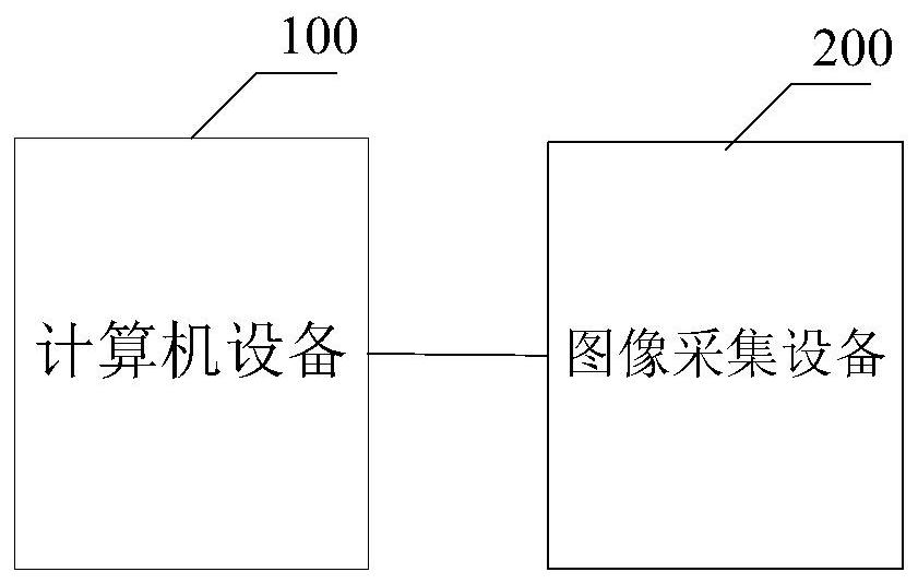
[0035] The application scene of the image stitching method provided by an embodiment of the present application may be a computer device or an image acquisition device. The computer device or the image acquisition device executes the image stitching method provided by an embodiment of the present application to stitch images captured by multiple cameras. A camera may belong to one image acquisition device, or may belong to multiple...


PUM


Abstract

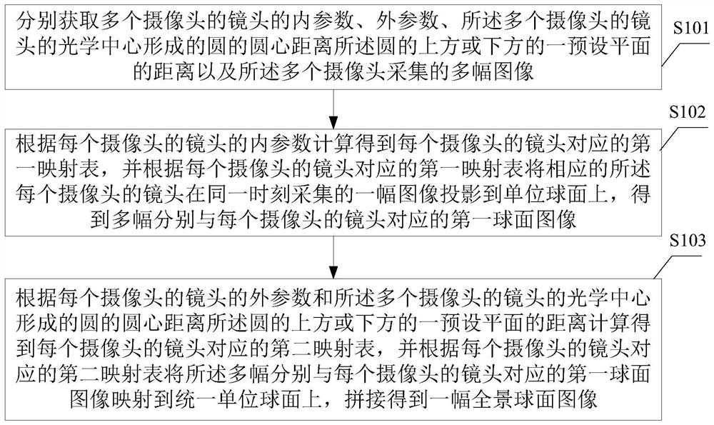
The invention is applicable to the field of image processing, and provides an image splicing method and device, a computer readable storage medium, computer equipment and a camera. The method comprises the following steps: calculating and obtaining a first mapping table corresponding to the lens of each camera according to the internal parameters of the lens of each camera, and projecting an image acquired by the lens of each corresponding camera at the same moment to a unit spherical surface according to the first mapping table, obtaining a plurality of first spherical images corresponding to the lens of each camera; according to the external parameters of the lens of each camera and the distance between the center of a circle formed by the optical centers of the lenses of the plurality of cameras and a preset plane above or below the circle, calculating and obtaining a second mapping table corresponding to the lens of each camera, and mapping the plurality of first spherical images to a unified unit spherical surface according to a second mapping table, and splicing and obtaining a panoramic spherical image. According to the invention, a more natural and real top and bottom spliced picture can be obtained.

Description

technical field [0001] The present application belongs to the field of image processing, and in particular relates to an image stitching method, device, computer readable storage medium, computer equipment and camera. Background technique [0002] The image stitching in the prior art is usually realized in the following way: firstly, the spherical coordinates of each pixel in the lens optical center as the center of the sphere are obtained through the internal parameters of the lens obtained through calibration; Position, where the amount of rotation of the rotation coordinates is obtained from the angular relationship (external parameters) between multiple lenses; after obtaining the mapping from a single picture pixel to a unified spherical coordinate, the pictures taken by each lens can be mapped to the spherical surface, Finally combined into a complete image. [0003] Because the positions of the optical centers of the lenses do not coincide, there is a parallax betwee...

Claims


Application Information

Patent Timeline
IPC IPC(8): G06T3/00G06T7/00G06T7/80G06T3/40H04N5/262H04N5/265
CPCH04N5/265H04N23/698H04N23/951H04N5/2628G06T3/4038G06T3/12G06T7/80G06V10/761G06V10/16H04N23/90G06T3/08G06T5/50G06T2207/20221
Inventor 苏坦高飞
Owner SHENZHEN ARASHI VISION CO LTD
Learn More