A remote electronic monitoring device

An electronic monitoring and equipment technology, applied in cooling/ventilation/heating renovation, cabinet/cabinet/drawer parts, support structure installation, etc. Ease of control and improved accuracy

Active Publication Date: 2021-06-04
JIANGXI UNIV OF TECH
View PDF0 Cites 0 Cited by
  • Summary
  • Abstract
  • Description
  • Claims
  • Application Information

AI Technical Summary

Problems solved by technology

[0003] In view of the above situation, in order to overcome the defects of the prior art, the present invention provides a remote electronic monitoring device, which effectively solves the problem of low monitoring accuracy caused by the fixed installation of the monitoring device in the above background technology

Method used


Image

  • A remote electronic monitoring device
  • A remote electronic monitoring device
  • A remote electronic monitoring device

Examples


Embodiment 1

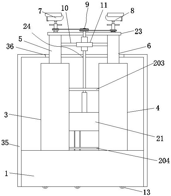
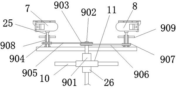
[0032] Embodiment one, by figure 1 , figure 2 , image 3 , Figure 4 , Figure 5 with Figure 7 Given, the present invention includes an installation housing 35, the top of the installation housing 35 is provided with a storage opening 36, and the bottom end of the installation housing 35 is fixedly connected with the installation base 1, and the inside of the storage opening 36 is interspersed with a lifting cylinder 5 and a lifting cylinder 2 6. The tops of lifting tube one 5 and lifting tube two 6 are connected by a base plate 23, two sides of the top of the base plate 23 are respectively provided with support rods two 25, and the tops of the two support rods 25 are respectively provided with monitoring one 7 and monitoring two 8, and a pull rod 10 is provided between the top of the lift tube 1 5 and the lift tube 2 6, and the middle position of the pull rod 10 is provided with a support base 11, and the support base 11 is provided with a monitoring device 7 and a moni...

Embodiment 2

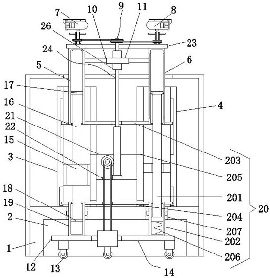
[0036] Embodiment two, on the basis of embodiment one, by figure 1 , figure 2 , Figure 4 and Image 6 Given, the supporting cylinder 1 3 and the supporting cylinder 2 4 are connected through the receiving seat 21, and the bottom end of the receiving seat 21 is provided with a through groove 1 22, which facilitates the movement of the later moving mechanism 14.

Embodiment 3

[0037] Embodiment three, on the basis of embodiment one, by figure 2 Given, both sides of the top of the support rod one 201 are embedded with balls, and the inner wall of the lifting cylinder two 6 is symmetrically provided with rolling grooves, thereby reducing the frictional force of movement.


PUM


Abstract

The invention relates to the technical field of electrical equipment structural parts, and discloses a remote electronic monitoring device, which solves the problem of low monitoring accuracy caused by the fixed installation of the monitoring device. There is a storage opening, and the bottom end of the installation shell is fixedly connected with the installation base, and the inside of the storage opening is interspersed with the first lifting cylinder and the second lifting cylinder, and the tops of the first lifting cylinder and the second lifting cylinder are connected through the base plate, and the two tops of the base plate The two sides are provided with support rod two, and the top of support rod two is provided with monitor one and monitor two respectively; through the design of pull rod one, support seat, moving mechanism, rotating block two, adjustment cylinder one and height adjuster, it is convenient to realize the installation of the device. Automatic movement increases the monitoring range of monitoring 1 and monitoring 2, realizes the all-round monitoring of monitoring 1 and monitoring 2, and then realizes the intelligent design of monitoring 1 and monitoring 2, greatly improving the accuracy of monitoring.

Description

technical field [0001] The invention belongs to the technical field of electrical equipment structural components, and in particular relates to remote electronic monitoring equipment. Background technique [0002] The existing electronic monitoring equipment used in remote monitoring often adopts a fixed installation method, which causes the monitoring range of the camera in the monitoring equipment to be easily blocked by external objects, resulting in a monitoring blind spot in the camera, which affects the comprehensiveness and accuracy of monitoring. Contents of the invention [0003] In view of the above situation, in order to overcome the defects of the prior art, the present invention provides a remote electronic monitoring device, which effectively solves the problem of low monitoring accuracy caused by the fixed installation of the monitoring device in the above-mentioned background technology. [0004] In order to achieve the above object, the present invention p...

Claims


Application Information

Patent Timeline
Patent Type & Authority Patents(China)
IPC IPC(8): H05K7/14H05K7/20H05K5/02
Inventor 熊蕾
Owner JIANGXI UNIV OF TECH
Why Eureka
Try Eureka